Hydraulic Drive Sizing for Crawler Undercarriages: Torque, Flow and Final Drive Ratio
Hydraulic drive sizing starts with the tractive effort the machine must produce, not with the motor catalogue. The correct sequence is: calculate required drawbar pull from mass, rolling resistance and gradient; convert it to wheel torque using the sprocket pitch radius; then select motor displacement and final drive ratio together; and only finally check flow, travel speed and heat rejection. Reversing that sequence — picking a motor first — is the most common reason a tracked machine is either underpowered on a ramp or unable to creep smoothly.
This article gives the calculation chain with a fully worked 20-tonne example, the efficiency assumptions that must be stated, and the checks that are usually missed on steel crawler undercarriages and custom tracked chassis.
1. Step One: Required Drawbar Pull
Total tractive effort is the sum of rolling resistance, gradient resistance and acceleration:
F = m·g·f + m·g·sinθ + m·a
Rolling resistance coefficient f for steel tracks is commonly taken in the range 0.05–0.10 on firm ground and higher in soft or rutted material; the value should be agreed for the actual site, not assumed. Note that a 20% gradient corresponds to sinθ ≈ 0.196, not 0.20 — a small distinction that is worth keeping straight in the arithmetic.
Worked example (illustrative, simplified for clarity): a 20,000 kg machine, f = 0.08, 20% gradient, gentle acceleration a = 0.1 m/s², g = 9.81 m/s².
| Term | Calculation | Result |
|---|---|---|
| Rolling resistance | 20,000 × 9.81 × 0.08 | 15,696 N |
| Gradient resistance | 20,000 × 9.81 × 0.196 | 38,455 N |
| Acceleration | 20,000 × 0.1 | 2,000 N |
| Subtotal | — | 56,151 N |
| Design margin (+15%) | 56,151 × 1.15 | 64,574 N (64.6 kN) |
| Per track | 64,574 / 2 | 32,287 N (32.3 kN) |
Before going further, check the adhesion limit. Available traction is roughly μ·m·g·cosθ; with μ ≈ 0.6 on firm soil this is about 115 kN, comfortably above 64.6 kN. On wet clay or loose sand, adhesion can become the binding constraint: adding motor torque will only spin the tracks. When that happens the answer is more contact area or lower ground pressure, not a bigger motor.
2. Step Two: Wheel Torque
With a sprocket pitch radius r = 0.25 m, the torque required at each drive wheel is:
Twheel = Fper track × r = 32,287 × 0.25 = 8,072 N·m
This is torque at the sprocket, after all gearing losses. Keep it separate from motor torque: the ratio between them is the final drive reduction multiplied by its mechanical efficiency. Two machines with identical wheel torque can use very different motor and reducer combinations, and the choice affects controllability, cost and heat.
3. Step Three: Motor Displacement and Reduction Ratio
A hydraulic motor's theoretical torque is Tmotor = Δp × V × ηm / 2π, where Δp is the pressure differential across the motor, V the displacement per revolution in m³, and ηm the mechanical efficiency. With Δp = 25 MPa, V = 80 cm³/rev (80 × 10−6 m³) and ηm = 0.92:
Tmotor = (25 × 106 × 80 × 10−6 × 0.92) / 6.283 ≈ 269 N·m
The required reduction ratio, with a gearbox efficiency ηg = 0.90, is:
i = Twheel / (Tmotor × ηg) = 8,072 / (269 × 0.90) ≈ 33.3
Select a standard planetary ratio of 35 and re-verify: 269 × 35 × 0.90 ≈ 8,474 N·m, which exceeds the 8,072 N·m requirement. A larger-displacement motor with a smaller ratio would also work, and generally gives smoother low-speed control; a small motor with a high ratio is more compact but can feel notchy at crawl speed. For machines with automated positioning, this trade-off deserves an explicit decision rather than a default.
4. Step Four: Flow, Speed and Power
Target travel speed v = 2 km/h = 0.556 m/s. Sprocket speed is nwheel = v / (2πr) = 0.556 / 1.571 ≈ 0.354 rev/s = 21.2 rpm. Motor speed is therefore 21.2 × 35 ≈ 742 rpm.
With volumetric efficiency ηv = 0.94, flow per track is Q = V × nmotor / ηv = 0.080 L × 742 / 0.94 ≈ 63 L/min, so about 126 L/min for both tracks. Hydraulic power at 25 MPa is approximately 25 × 106 × 0.0021 m³/s ≈ 52.5 kW, while useful mechanical power is 64,574 × 0.556 ≈ 35.9 kW. The difference is the combined mechanical, volumetric and gearing loss that ends up as heat in the oil.
That last number is why the thermal check is not optional. On a machine working a continuous duty cycle in a warm climate, the oil cooler, reservoir volume and allowable operating temperature must be sized against this loss. Undersized cooling leads to viscosity loss, increased internal leakage and a gradual loss of tractive effort during the shift.
5. Control, Differentials and Two-Track Behaviour
Sizing for straight-line pull is only part of the job. Confirm the following with the drive supplier:
- Turning torque — skid steering and counter-rotation can demand substantially more torque per track than straight travel, especially on high-friction surfaces.
- Brake holding — the negative multi-disc parking brake must hold the machine on the specified gradient with the rated load, and its release circuit must be independent of main supply pressure for towing.
- Flow sharing — with two motors in parallel from one pump, the lower-resistance track tends to run away on a bend. A flow divider or independent closed-loop pumps changes the behaviour.
- Closed vs open circuit — closed-loop hydrostatic transmission gives better dynamic braking and finer control; open circuits are simpler and easier to service. The choice should follow the duty cycle.
- Case drain and cooling — motor case drain flow, back-pressure limit and flush valve settings belong in the schematic, not in an appendix.
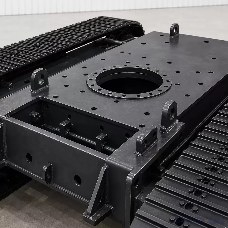
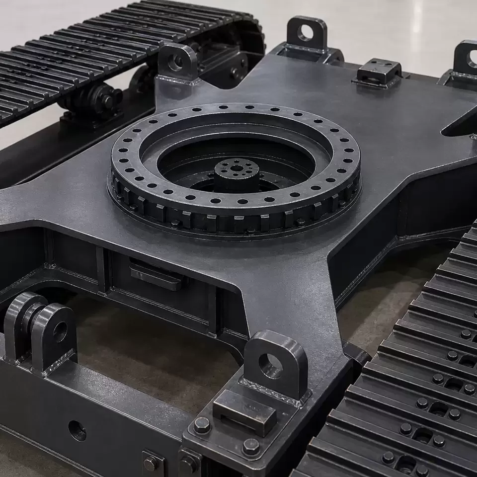
Where the upper structure supplies the hydraulics, the OEM/ODM interface must state flow, pressure, port standard and case drain routing. Sizing a chassis drive against an assumed pump is a frequent source of commissioning problems.
6. Common Sizing Mistakes
| Mistake | Consequence | Correction |
|---|---|---|
| Using machine mass only, ignoring gradient and acceleration | Machine stalls on the first ramp | Build the full force sum and add a design margin |
| Specifying motor torque without stating Δp | Quoted torque is unavailable at the operating pressure | Always state pressure differential and efficiency assumptions |
| Ignoring gearbox efficiency in the ratio calculation | Selected ratio delivers 10–15% less wheel torque than expected | Divide by ηg explicitly |
| Checking top speed but not continuous thermal balance | Performance fades as oil heats up | Size cooling from the calculated loss |
| Choosing a very high reduction ratio for compactness | Poor low-speed control and high backlash | Balance ratio against controllability for the duty cycle |
| Forgetting sprocket, chain and roller load limits | Drivetrain is capable but the track group wears rapidly | Check component ratings against the same load case |
Frequently Asked Questions
What pressure should be used for the sizing calculation?
Use the continuous pressure differential available at the motor under load, not the pump's maximum relief setting. Sizing against relief pressure produces a drive that only meets the requirement at a setting the machine should never run at continuously.
Why not simply fit a bigger hydraulic motor?
A larger displacement motor delivers more torque at the same pressure but needs more flow for the same speed, and it changes low-speed resolution. Motor displacement, reduction ratio and pump flow have to be selected as a set.
How much design margin is appropriate?
A margin of roughly 15–25% over the calculated tractive effort is common for the steady load case, with turning, transient shock and adhesion checked separately. Excessive margin increases flow, heat and cost without improving usable performance once adhesion is the limit.
Related Products and Next Step
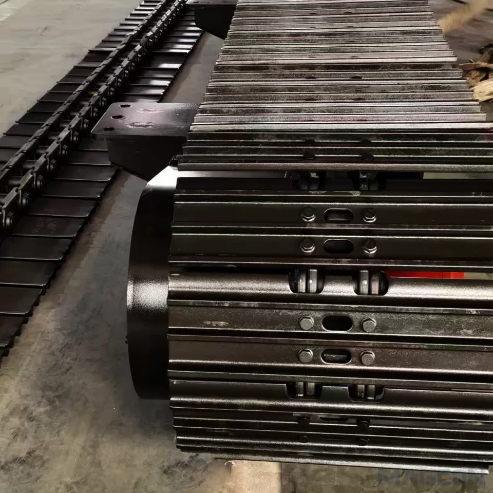
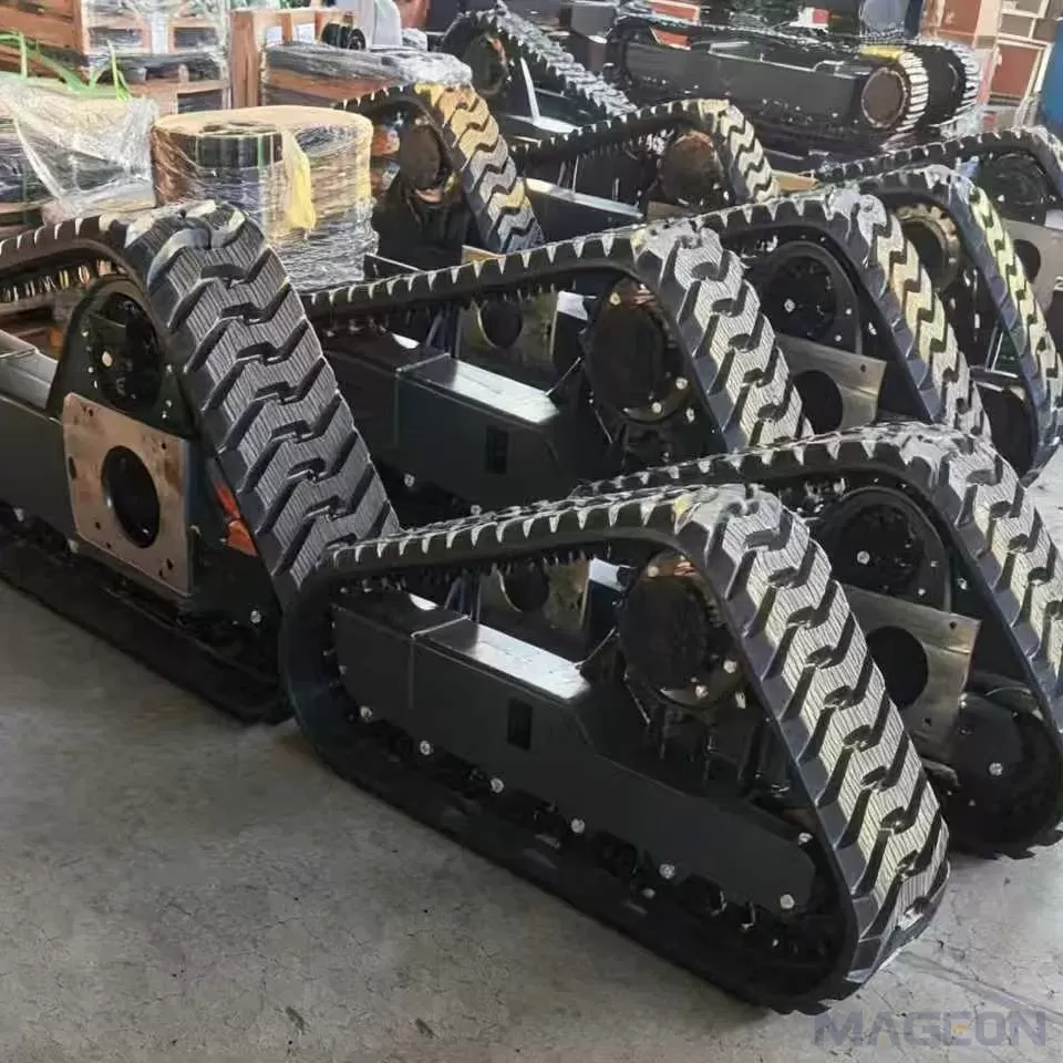
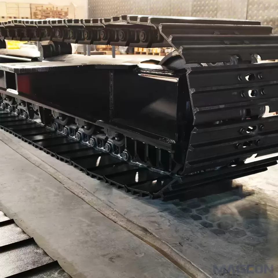
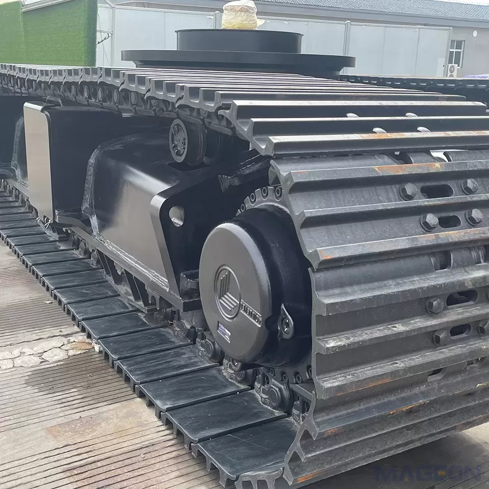
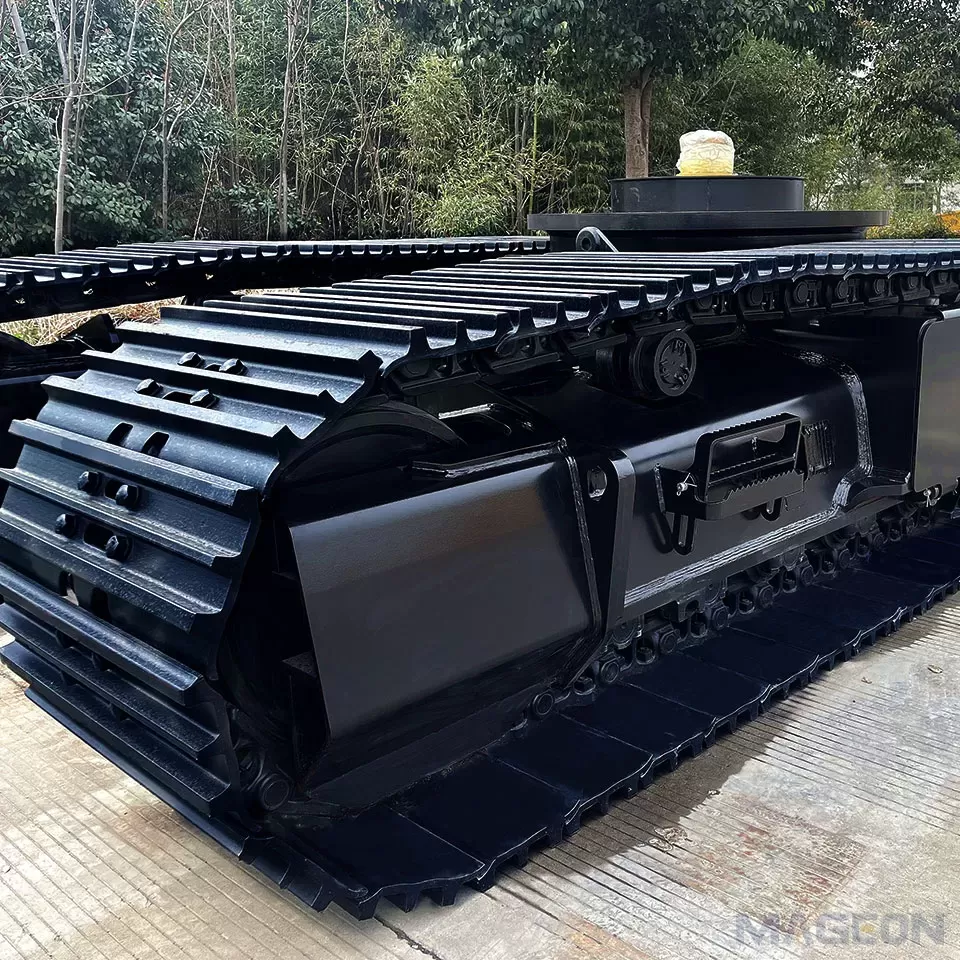
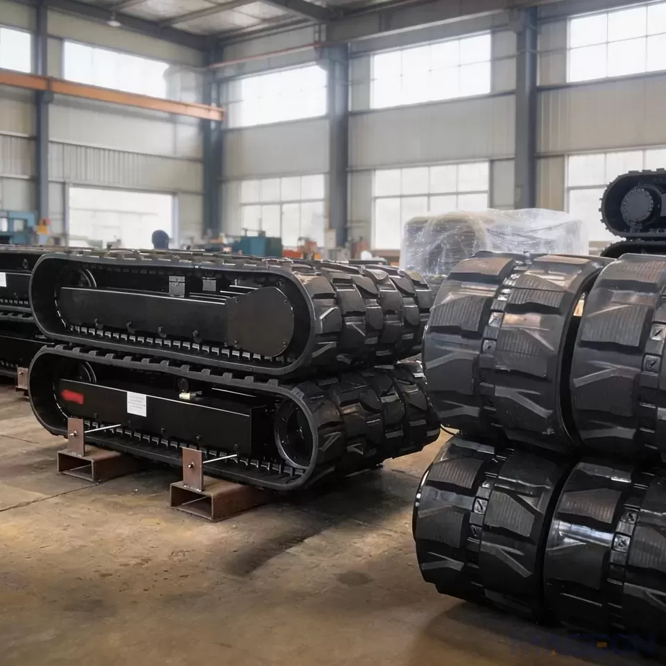
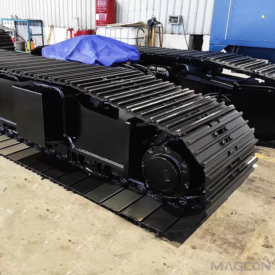
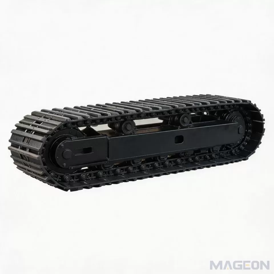
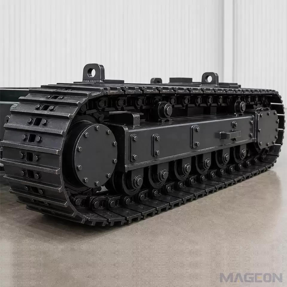
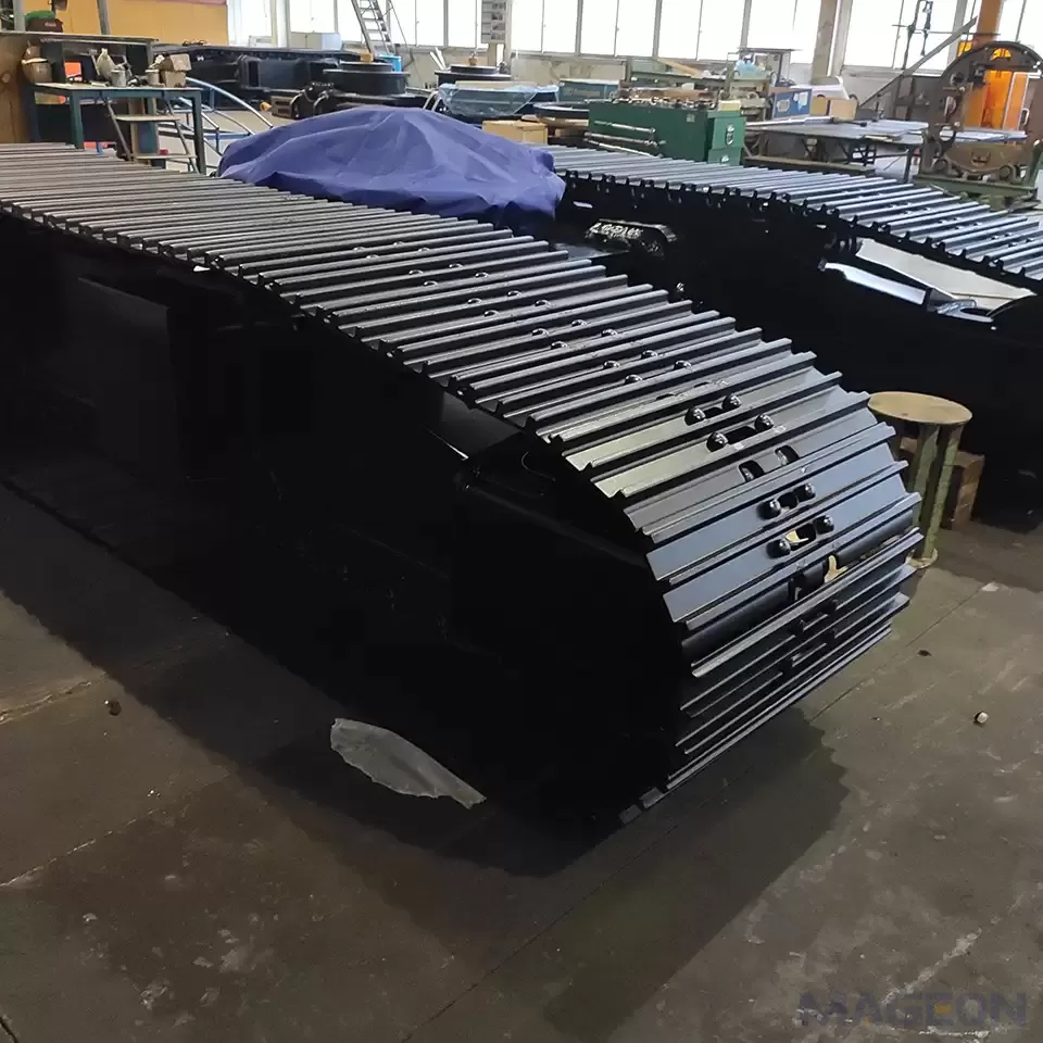
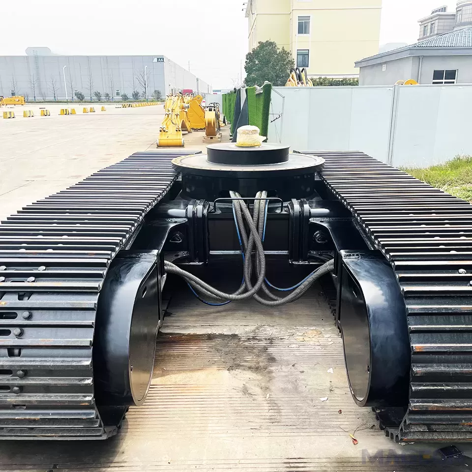
MAGEON engineers hydraulic drive packages for steel crawler undercarriages, drilling rig undercarriages and custom tracked chassis, and supplies matched sprockets, chains and rollers. Send the working mass, maximum gradient, target travel speed, available pump flow and pressure, and duty cycle; we will return the tractive effort calculation, motor and ratio selection, and the thermal balance as part of the OEM/ODM design package.
Please leave your customization requirements, and we will contact you as soon as possible!
Leave your requirements, we'll get back to you within 24 hours.