Welding Procedure Qualification for Crawler Undercarriage Frames: WPS, PQR and Distortion Control

A crawler undercarriage frame is a fatigue-loaded welded structure whose dimensional accuracy determines whether the upper structure will fit. Welding procedure qualification (WPS supported by a PQR), controlled weld sequencing and appropriate non-destructive testing are therefore not paperwork: they define the fatigue strength of the joint, the residual stress in the frame, and the flatness of the machined mounting face. A frame can pass a static load test and still fail early in service because the weld toe geometry or the heat input was never controlled.
This article describes what an OEM should ask to see in a steel crawler undercarriage welding quality package, and how distortion control links to the mounting interface described in our interface specification guide.
1. WPS and PQR: What the Documents Actually Prove
A Welding Procedure Specification (WPS) is the instruction the welder follows. A Procedure Qualification Record (PQR, also called WPQR) is the test evidence showing that following that instruction produces a joint with the required properties. Qualification is normally carried out to EN ISO 15614-1 for arc welding of steels, or to ASME Section IX where the project uses that code; welder qualification is a separate document, commonly EN ISO 9606-1.
The essential variables that must be stated and controlled include:
| Variable | Why it matters for an undercarriage frame |
|---|---|
| Base material grade and thickness range | Determines toughness, preheat requirement and the qualified thickness window; a WPS qualified on thin coupon does not automatically cover a 40 mm box section |
| Filler metal classification and hydrogen class | Controls hydrogen-induced cracking in thick, restrained joints and the toughness of the weld metal at low temperature |
| Preheat and interpass temperature | Prevents cold cracking and controls the cooling rate that sets the heat-affected-zone microstructure |
| Heat input (kJ/mm) | Excessive input coarsens the grain structure and reduces toughness; too little risks lack of fusion |
| Welding position, polarity, travel speed, shielding gas | Changes penetration profile and defect population; production conditions must stay within the qualified range |
| Post-weld heat treatment, if any | Relieves residual stress but can degrade the properties of quenched and tempered or fine-grain low-temperature steels if applied incorrectly |
Ask for the PQR's mechanical test results — tensile, bend and, for low-temperature machines, Charpy impact values at the specified test temperature. A certificate number without the underlying test values tells you very little about a safety-critical frame.
2. Why Distortion Control Is a Functional Requirement
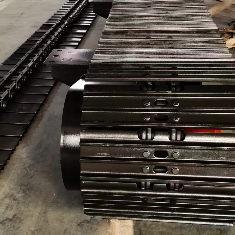
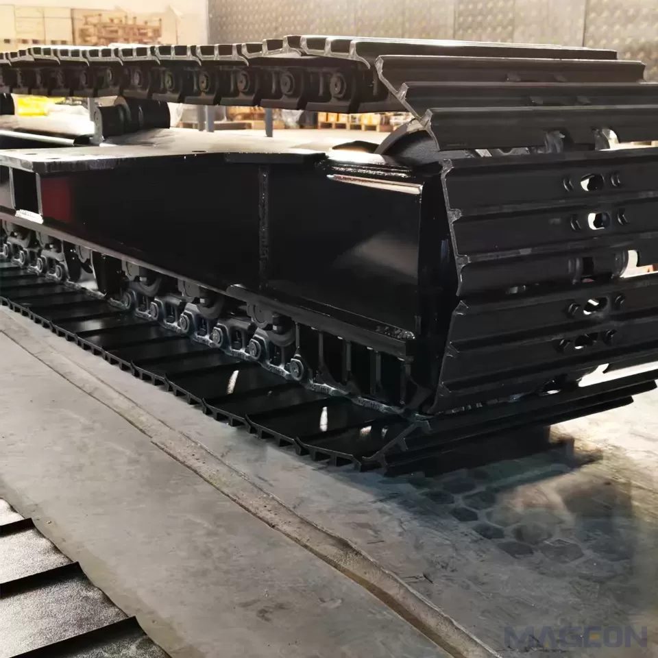
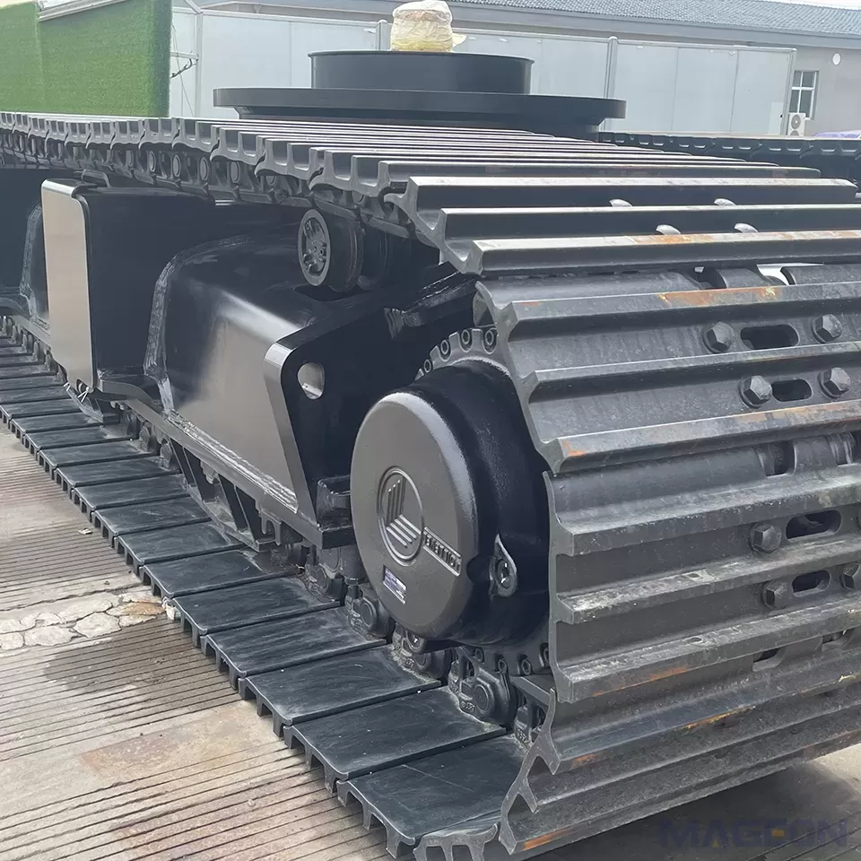
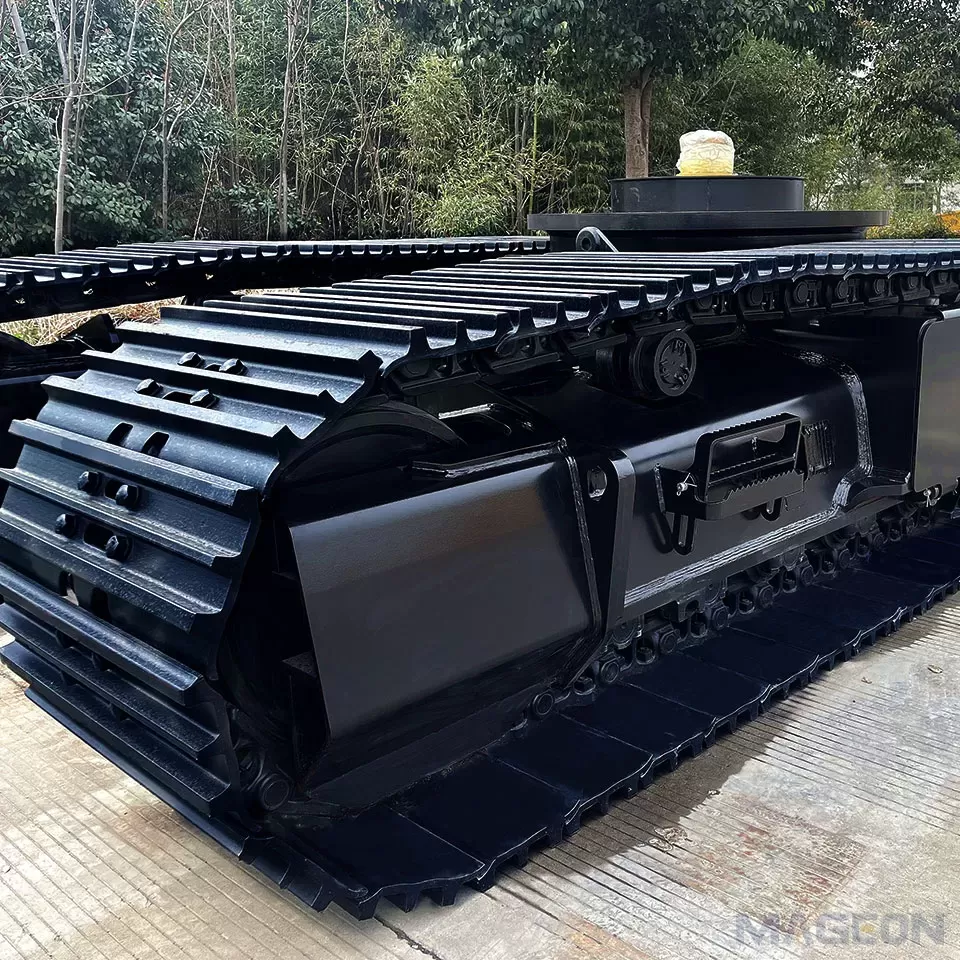
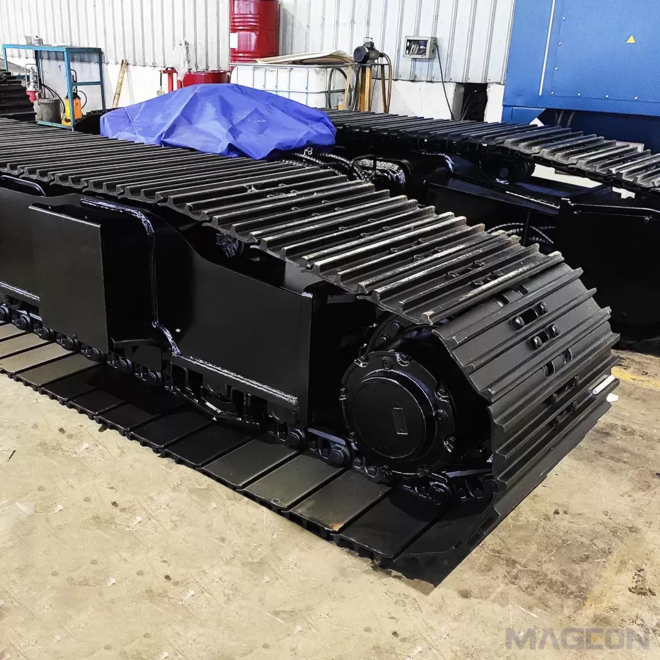
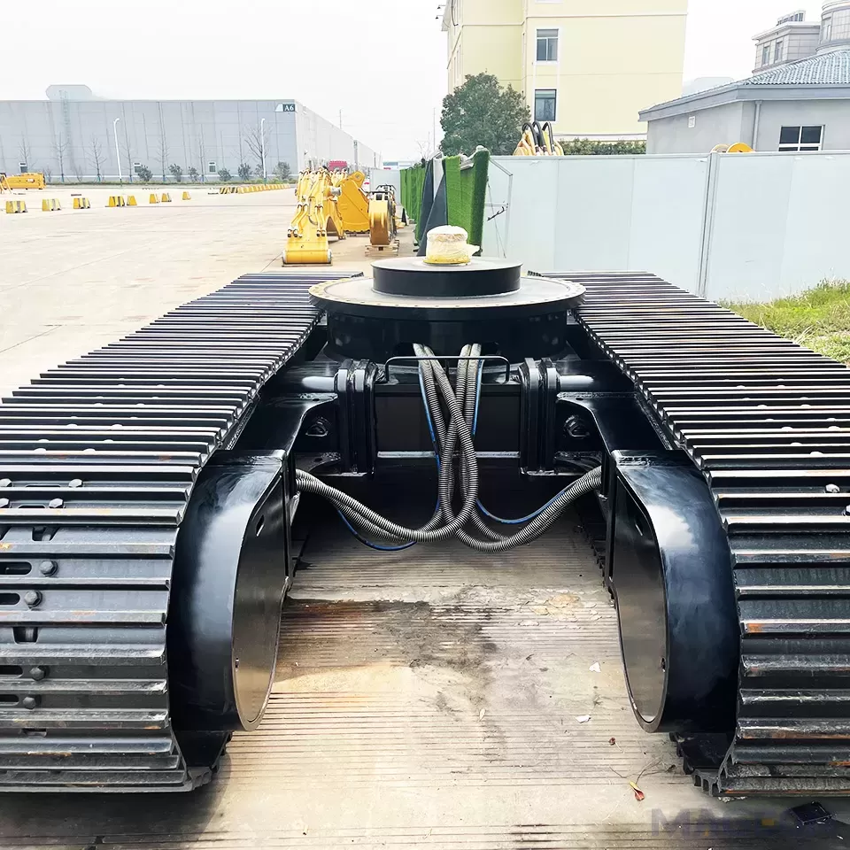
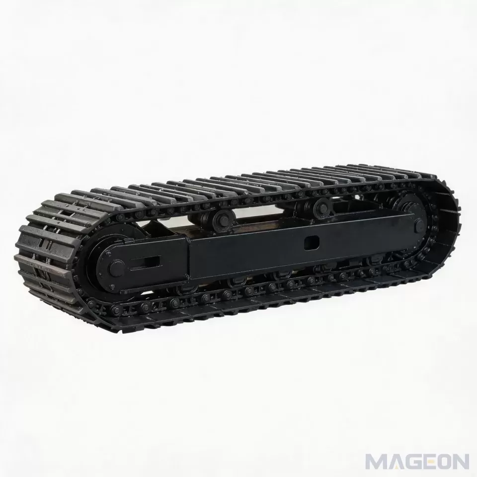
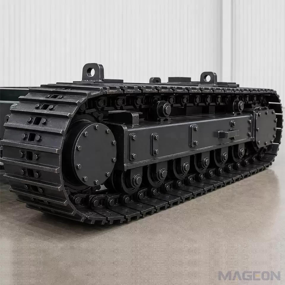
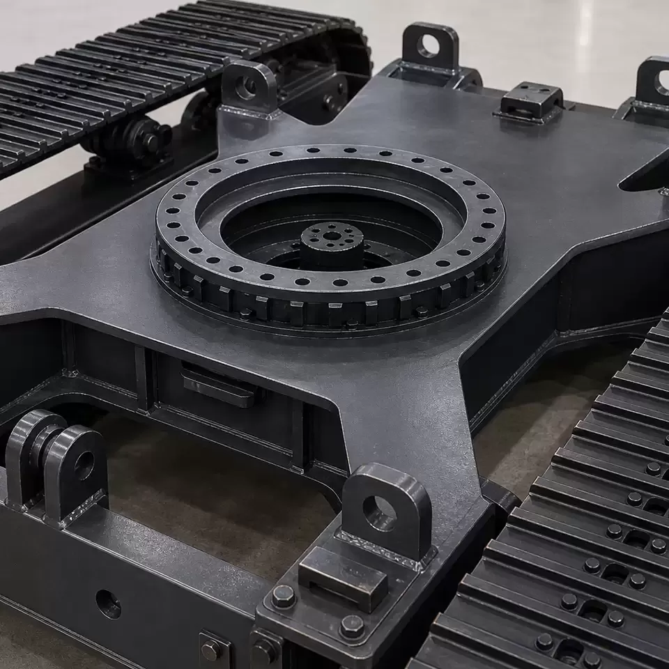
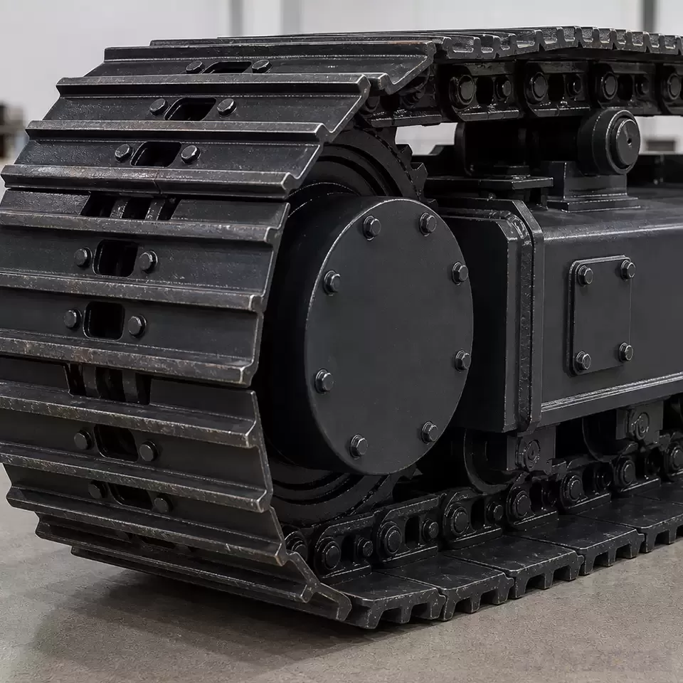
The track frame carries the rollers, idlers and final drive on aligned axes. If the frame twists during welding, roller alignment drifts, the chain runs off-centre, and wear accelerates on one side. At the same time, the machined mounting pads for the upper structure must be flat and coplanar. Both depend on how the weldment is sequenced and fixtured.
Practical controls include:
- Balanced weld sequencing — weld symmetrically about the neutral axis, alternating sides so shrinkage on one face is offset by the other.
- Back-step and segmented runs — reduce longitudinal shrinkage on long box-section seams compared with a single continuous run.
- Preset / anti-deformation — fixture the assembly with a calculated counter-camber so it relaxes into tolerance.
- Restrained but not over-constrained fixturing — excessive restraint raises residual stress even if the part measures correctly in the jig; it can spring out of tolerance when released.
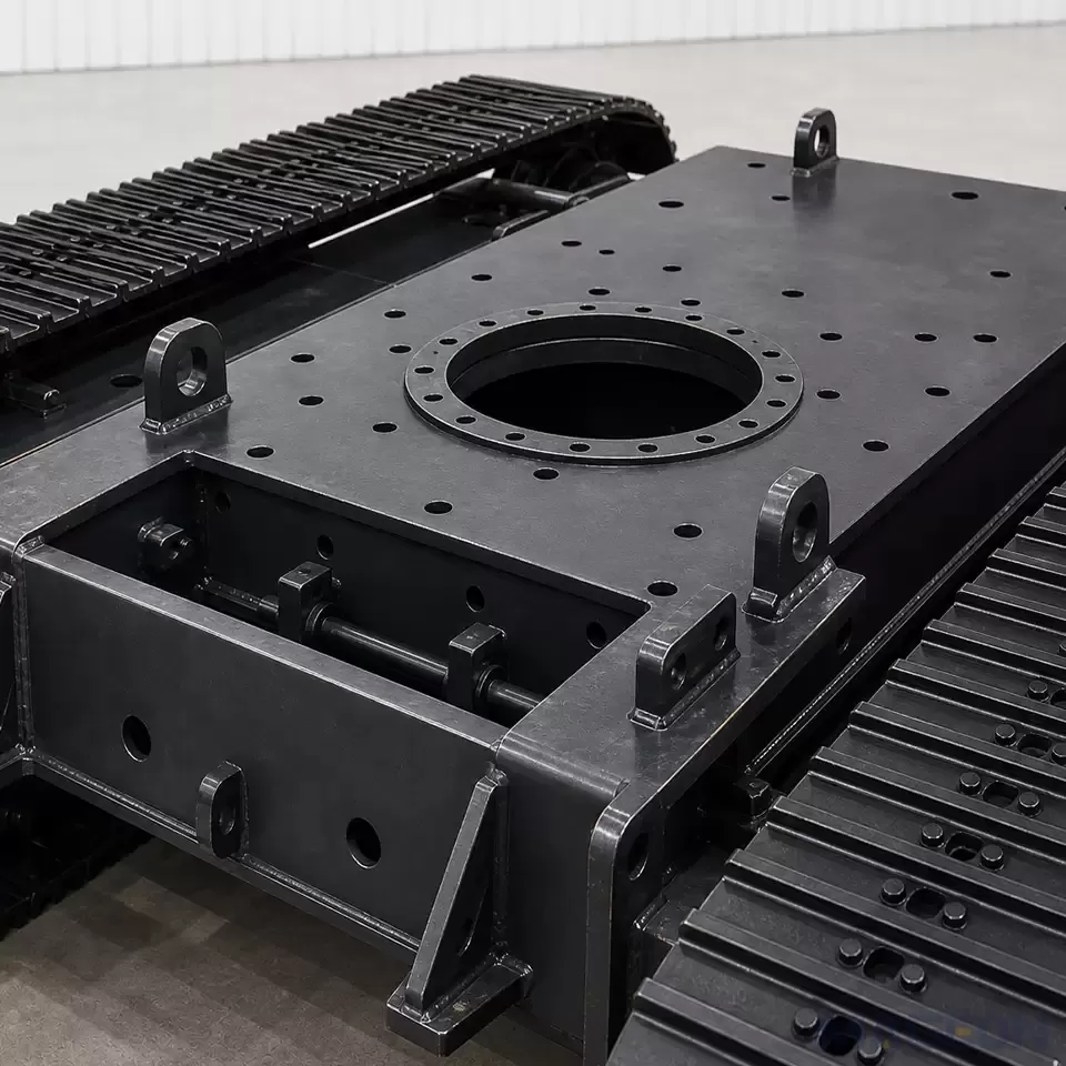
- Machine critical faces after welding — mounting pads, bearing seats and roller bores should be finish-machined after welding and stress relief, using a defined datum scheme.
- Record the as-built measurement — flatness, parallelism and track gauge measured after the frame is released from the fixture, not while clamped.
This is the manufacturing counterpart of the interface drawing: the drawing specifies the datum, and the welding and machining plan is what makes that datum achievable in production.
3. Fatigue Detail Design
Undercarriage frames see millions of low-amplitude load cycles from travel over uneven ground, plus occasional high-amplitude events from impact and slew reversal. Fatigue strength is governed less by the nominal stress than by the local weld detail. The design should therefore:
- Avoid weld intersections, abrupt section changes and ungrounded weld starts/stops in high-stress regions.
- Place full-penetration butt welds away from the peak bending moment of the cross-member where possible.
- Specify a defined weld quality level (for example EN ISO 5817 quality level B or C for the relevant imperfections) and state which joints are fatigue-critical.
- Consider weld toe improvement — TIG dressing, grinding or hammer peening — on the highest-loaded details, and record it as a controlled process rather than an operator option.
- Provide smooth load transitions from the mast or upper structure mounts into the cross-members; a hard stiffness step concentrates stress at the weld toe.
Where finite element analysis is used, check that the model represents the weld detail category being assumed. A global model with idealised rigid joints will not predict the local stress at a weld toe, which is where cracks normally start.
4. Non-Destructive Testing Plan
Testing should be specified by joint criticality, not applied uniformly. A typical plan includes 100% visual examination (VT) of all welds, magnetic particle testing (MT) or penetrant testing (PT) of fillet welds and accessible surfaces on fatigue-critical joints, and ultrasonic testing (UT) of full-penetration butt welds in the main load path, with acceptance levels referenced to a named standard (for example EN ISO 11666 for UT or EN ISO 23279 for MT).
Ask for the examination extent, the acceptance level, the personnel qualification (for example ISO 9712 Level 2), and the traceability between the weld map and the report. A report that lists "UT passed" without a weld identification map is difficult to use when a field crack later needs to be correlated with the original fabrication record.
5. Traceability and the Export Documentation Package
For machines placed on regulated markets, the fabrication record is part of the technical file. A coherent package normally contains material certificates (EN 10204 type 3.1 for structural plate), filler metal batch records, the WPS/PQR set, welder qualifications, NDT reports with a weld map, the dimensional inspection report after machining, and the coating record with surface preparation grade and dry film thickness.
These documents are easiest to assemble while the frame is being built. Retrofitting traceability after shipment is slow and often impossible, so specify the deliverables at the quotation stage. MAGEON's OEM/ODM engineering service can align the welding and inspection package with the buyer's technical file requirements before production begins.
Frequently Asked Questions
Is a WPS alone enough to qualify a supplier?
No. A WPS is an instruction; the PQR is the test evidence that the instruction produces acceptable properties, and the welder qualification confirms the operator can follow it. All three, plus the NDT record, are needed for a critical frame.
Does post-weld heat treatment always improve a track frame?
Not always. It reduces residual stress, but it can degrade the mechanical properties of quenched and tempered or fine-grain low-temperature steels if the temperature and holding time are not matched to the grade. The decision belongs in the qualified procedure, not in a general workshop rule.
Why are mounting pads machined after welding?
Because weld shrinkage changes the position and flatness of as-welded surfaces. Machining against a defined datum after welding and stress relief is what guarantees the interface drawing dimensions on the finished frame.
Related Products and Next Step
MAGEON manufactures steel crawler undercarriages and custom tracked chassis with qualified welding procedures, controlled machining datums and documented inspection, and supplies matching undercarriage parts. For an export project, state the applicable standard, the weld quality level, the required NDT extent and the documentation list in your enquiry; our OEM/ODM team will confirm what can be supplied before the order is placed.
Please leave your customization requirements, and we will contact you as soon as possible!
Leave your requirements, we'll get back to you within 24 hours.