How to Define the Mounting Interface Between a Crawler Undercarriage and an OEM Upper Structure
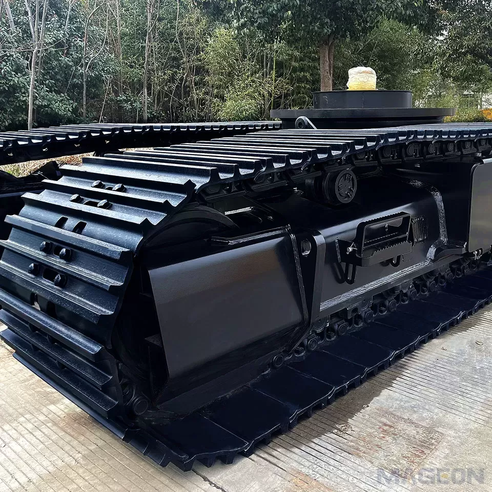
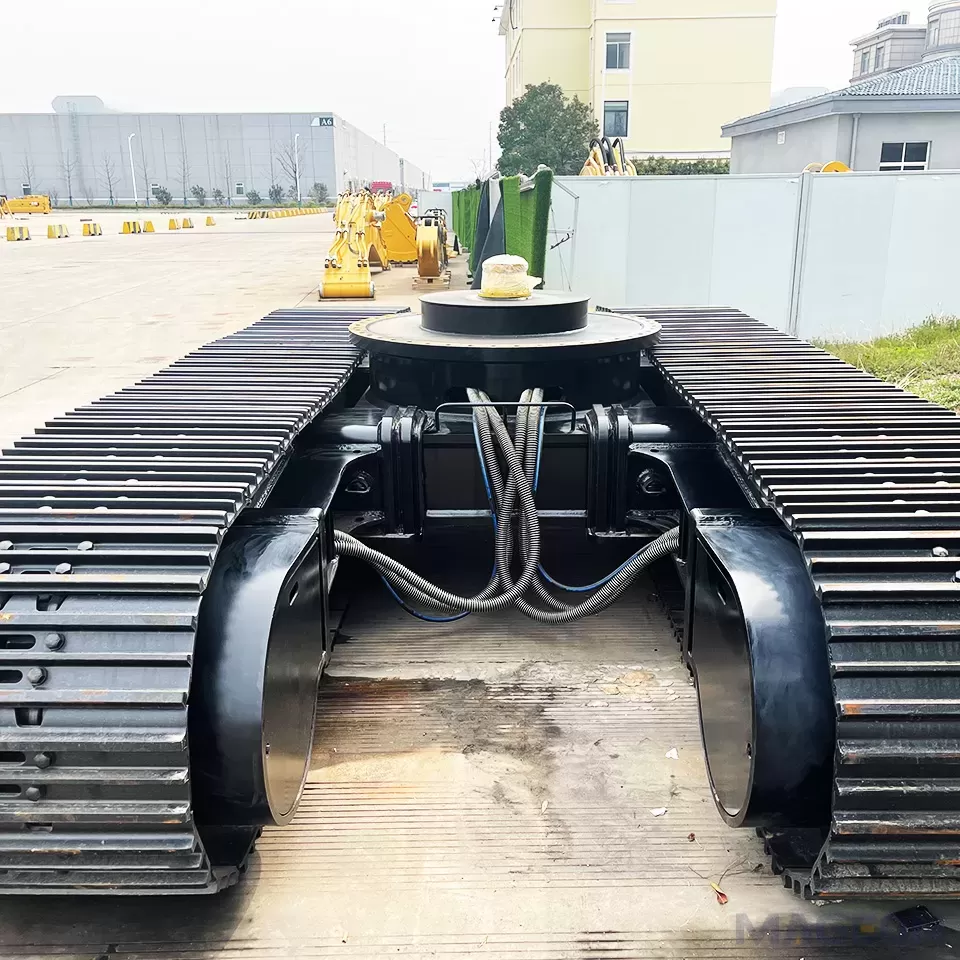
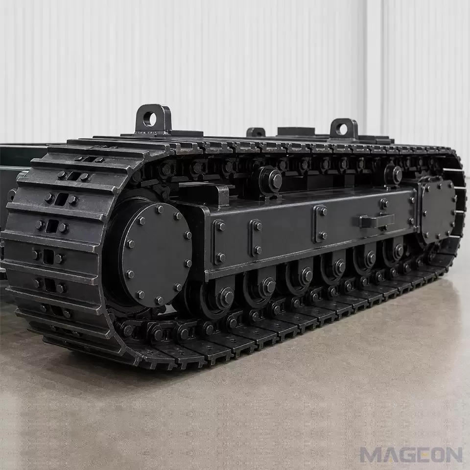
The mounting interface is the complete set of mechanical, hydraulic and electrical connection points between a crawler undercarriage and the machine built on top of it. Defining it in writing — bolt pattern, load path, datum scheme, centre-of-gravity envelope, hose routing, connector type and tolerance stack — is the single most effective way to prevent a custom chassis from arriving on site and failing to mate with the upper structure it was designed for. In most OEM projects, interface errors cost more time than any manufacturing step, because they are discovered only at the assembly stage.
This guide sets out the information an OEM should freeze before releasing a custom tracked chassis for tooling, and the documentation that should come back from the undercarriage supplier before the first production unit is built.
1. Treat the Interface as a Separate Engineering Deliverable
A crawler undercarriage is rarely a stand-alone product. It is a load-bearing module that accepts an upper structure supplied by another engineering team, often in another country. The two teams may use different CAD origins, different units, and different assumptions about which part carries which load. Without a controlled interface document, each team optimises its own half and the mismatch appears at the mating face.
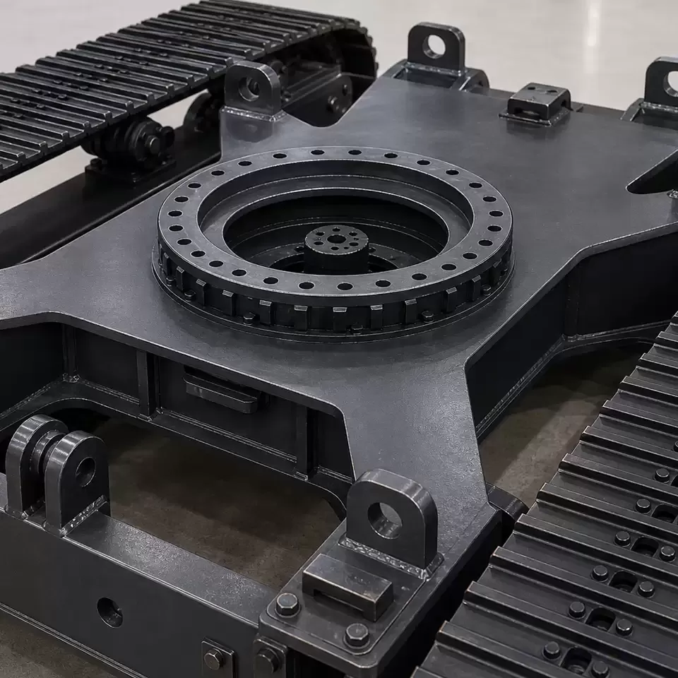
The practical consequence is that the interface should be a signed-off drawing package in its own right, with a revision number, a datum scheme and a change-control process — not a note buried in a purchase order. On projects where the upper structure slews, the interface also includes the slew bearing and its bolt circle, which makes it a safety-critical structural joint rather than a simple bolted flange.
2. The Mechanical Interface: Eight Items to Freeze
The following table is the minimum set of mechanical parameters that should appear on the controlled interface drawing. Every item has a corresponding failure mode when it is left undefined.
| Interface item | What must be specified | Typical failure if omitted |
|---|---|---|
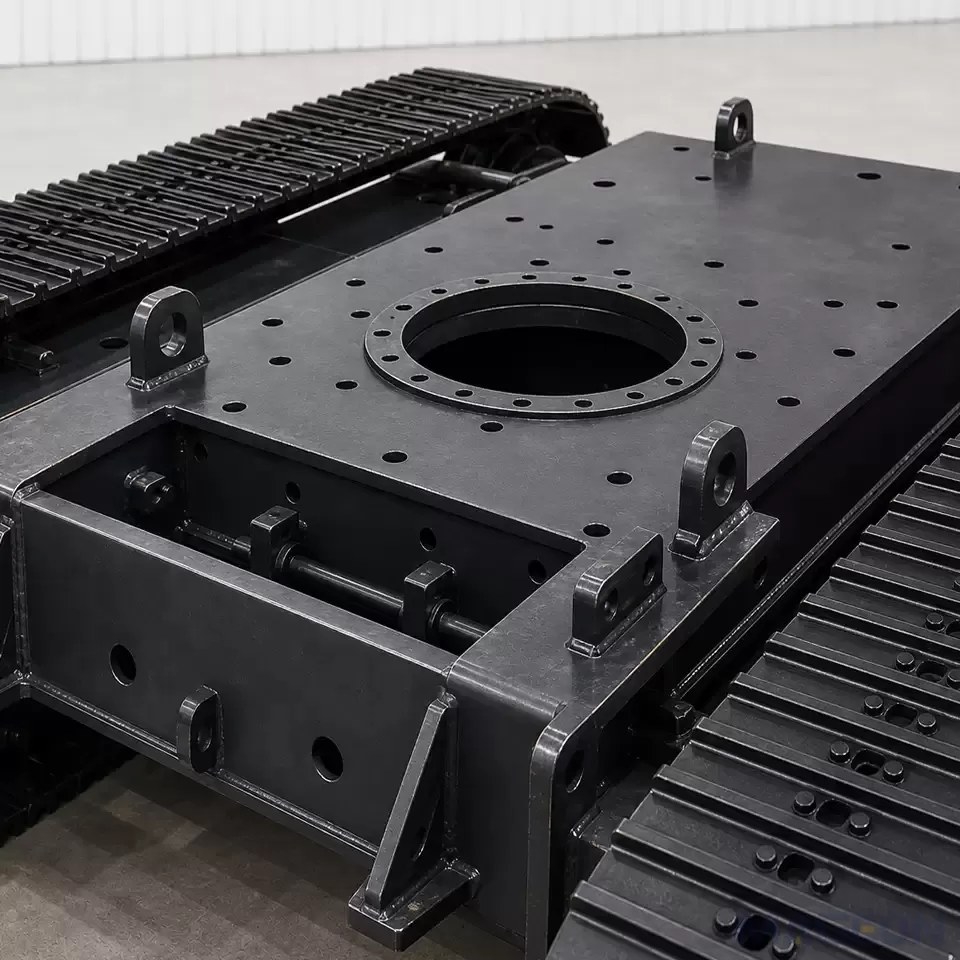
| Mounting plane and datum | Three-datum scheme (A/B/C), flatness tolerance, surface finish, and the exact Z height of the mating face | Upper structure rocks on the frame; bolt preload relaxes in service |
| Bolt pattern | Hole count, pitch-circle diameter, hole diameter and tolerance, counterbore requirements, threaded vs through-hole | Assembly cannot be bolted; field drilling damages heat treatment or coatings |
| Fastener specification | Grade (e.g. ISO 898-1 class 10.9), diameter, grip length, tightening torque, tightening sequence, thread lubricant | Joint slip under reversing loads, fatigue cracking around holes |
| Load cases | Static vertical load, dynamic factor, braking and slewing torque, side load on slopes, lifting/transport tie-down loads | Frame sized for weight only; cracks appear at the cross-member welds |
| Centre of gravity envelope | Maximum permitted CG offset in X and Y, and CG height, including attachments and fuel or counterweight states | Machine tips on the design gradient; tip-over margin is lost |
| Slew bearing interface | Bearing type, bolt circle, gear module and position, lubrication access, seal orientation | Bearing cannot be greased after assembly; ring gear meshes incorrectly |
| Mass and transport limits | Total chassis mass, split into shippable sub-assemblies, lifting points, maximum transport width and height | Unit exceeds road transport envelope or cannot be lifted by the receiving workshop |
| Corrosion and coating boundary | Which surfaces are masked before welding, coating system, and which mating faces remain uncoated | Paint thickness changes the datum; slip-critical joints lose friction |
Where the upper structure is still at concept stage, the most useful single document is a reservation drawing: an envelope drawing showing the space the undercarriage must not intrude into, plus the space the upper structure must keep clear for track frame movement, tensioning travel and hose swing. Both teams can work in parallel against it.
3. Hydraulic and Electrical Interfaces
Mechanical fit gets most of the attention, but hydraulic and electrical mismatches cause more commissioning delays. The interface document should state:
- Supply and return — working pressure, continuous and peak flow per track, port size and thread standard, flange standard (for example SAE J518 / ISO 6162), and whether the case drain returns separately to tank.
- Quick couplings — type and standard (for example ISO 16028 flat-face), male/female orientation on each half, and colour or key coding so the two tracks cannot be crossed.
- Brake release — the pressure and port used to release the negative multi-disc parking brake, and the safe towing procedure if no external release is provided.
- Control signal — proportional solenoid voltage and current, PWM frequency, connector pinout, and whether the chassis controller expects CAN (J1939 / CANopen) or discrete signals.
- Sensors — speed, pressure and temperature sensor outputs, supply voltage, and which values are expected to be displayed on the upper structure HMI.
For a steel crawler undercarriage with a hydraulic final drive, confirm the reduction ratio and the motor displacement together. A mismatch here cannot be corrected with hose changes: it changes travel speed, drawbar pull and the torque reflected into the track frame.
4. Tolerance Stack and the Datum Scheme
A datum scheme is what turns two independently manufactured assemblies into one machine. Specify a primary mounting plane, a secondary locating feature (usually two dowel holes or a machined keyway), and a tertiary stop that fixes rotation. Avoid locating on as-welded surfaces: welded track frames move during stress relief and machining, so the drawing should call out which faces are machined after welding.
Then run the tolerance stack across the whole assembly: frame flatness, machined pad height, bearing ring flatness, upper structure baseplate flatness and bolt grip length. A stack that looks acceptable on individual parts can still exceed the bearing manufacturer's flatness limit once assembled. Where the slew bearing is involved, use the bearing supplier's own mounting-face specification as the controlling requirement, because bearing warranties are written against it.
5. Documentation to Request Before Tooling Release
Before the supplier cuts material, ask for a package that can be checked by the upper-structure team without interpretation:
- 2D interface drawing, fully dimensioned, with revision and signature blocks
- 3D model in a neutral format (STEP) with the same origin and axis convention as the upper structure
- Load case table and, where relevant, finite element results for the mounting region
- Hydraulic circuit schematic with port identification matching the physical markings
- Wiring pinout and CAN message list, if a chassis controller is supplied
- Bolt torque specification, tightening sequence and re-torque interval
- Transport drawing showing split lines, lifting points and shipping dimensions
Ask that every dimension on the interface drawing be traceable to a single revision. Mixed-revision drawings are a common source of mismatched bolt circles, and they are difficult to detect until physical assembly.
6. Interface Review Checklist
A short formal review catches most problems. Walk through the following with both engineering teams present:
- Does the CG envelope cover every operating configuration, not just the transport configuration?
- Are all load cases defined with a dynamic factor, including braking and slew reversal?
- Is there physical access to grease the slew bearing and to inspect track rollers, idlers and sprockets after the upper structure is fitted?
- Can the track tensioning adjuster be reached with the machine fully assembled?
- Is the hydraulic hose swing envelope clear of the slew radius and of hot surfaces?
- Does the transport split line fall where the workshop actually intends to split the machine?
Frequently Asked Questions
What is the most common cause of an undercarriage not fitting the upper structure?
An undefined or inconsistently revisioned datum scheme. The two assemblies are each built correctly to their own drawing, but the mounting planes, bolt circles or axis origins were never fixed in a shared, controlled interface document.
Should the slew bearing be supplied with the undercarriage?
It can be, but the important point is that one party owns the bearing specification and the mating-face flatness on both sides. Splitting that responsibility between two suppliers without a shared drawing is what leads to premature bearing failure.
Can an existing undercarriage be adapted to a new upper structure?
Often yes, through a machined adapter frame, but the adapter adds height and moves the centre of gravity upward. Recheck the tip-over margin and the load path into the cross-members before approving it. For a new machine, designing the interface from the start is almost always cheaper.
Related Products and Next Step
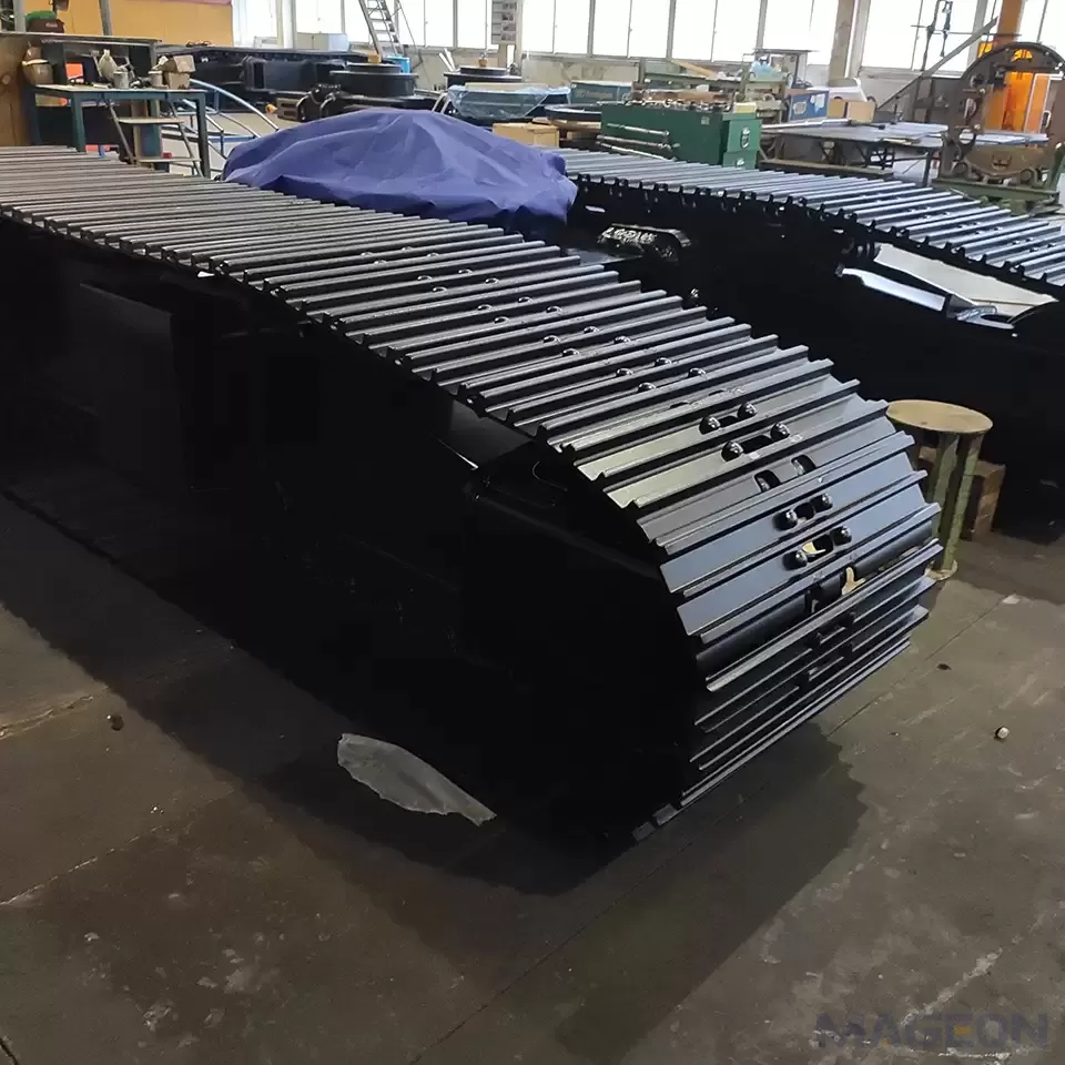
MAGEON builds custom tracked chassis to an agreed interface drawing, and supplies steel crawler undercarriages and drilling rig undercarriages for OEM integration. Our OEM/ODM engineering service covers 3D models, load calculations and interface drawings as part of the design package. To start a project, send the upper structure mass and CG envelope, the intended mounting plane and bolt pattern, and the hydraulic supply parameters; the interface drawing is normally the first deliverable we agree before any tooling is released.
Please leave your customization requirements, and we will contact you as soon as possible!
Leave your requirements, we'll get back to you within 24 hours.