
How Does Track Gauge Affect Crawler Machine Packaging, Turning, and Stability?
Track gauge affects a crawler machine in three connected ways: it changes the lateral packaging envelope, enters the geometry of skid-steer turning, and contributes to the machine's lateral support geometry. It does not, by itself, determine overall width, real turning radius, turning resistance, or stability. Those outcomes also depend on track shoe width, ground-contact length, mass distribution, centre of gravity, attachments, track speeds, terrain and operating state.
For an OEM, the practical decision is therefore not “wide or narrow?” It is whether the proposed gauge fits the complete machine envelope and leaves enough engineering margin for the required manoeuvres and working conditions. The answer must be verified with project drawings, configuration-specific mass and centre-of-gravity data, and representative operating conditions.
Separate Track Gauge from Other Crawler Dimensions
In tracked-vehicle kinematics, track gauge commonly means the lateral distance between the axes of the left and right tracks. The International Organization for Standardization's ISO 6746-1 provides a reference and coding framework for dimensions of earth-moving base machines. For machines outside that scope—or whenever supplier drawings use a different datum—the project team should state the exact reference lines and measurement condition instead of relying on an unlabeled value.
Four dimensions are often discussed together, but they answer different questions:
| What it describes | Why it matters | Project confirmation | |
|---|---|---|---|
| Track gauge | Lateral separation between the left- and right-track reference axes | Chassis layout, turning geometry and lateral support geometry | Confirm axes, datum and machine condition on the approved drawing |
| Track shoe width | Width of one track shoe or belt | Contact geometry, side clearance and outer envelope | Confirm the actual track configuration and any protruding features |
| Overall machine width | Outermost lateral extent of the complete machine | Transport, access, guarding and site restrictions | Check the complete machine in relevant static and operating states |
| Ground-contact length | Longitudinal length of track contact used for the defined condition | Ground interaction and turning resistance models |
Track gauge and track shoe width may both contribute to overall width, but the final envelope can also be affected by frames, fasteners, guards, motors, hoses or attachments. A supplier should not infer the allowable gauge from an overall-width limit without seeing how that limit is measured and which components define the outermost points.
How Track Gauge Changes the Packaging Envelope
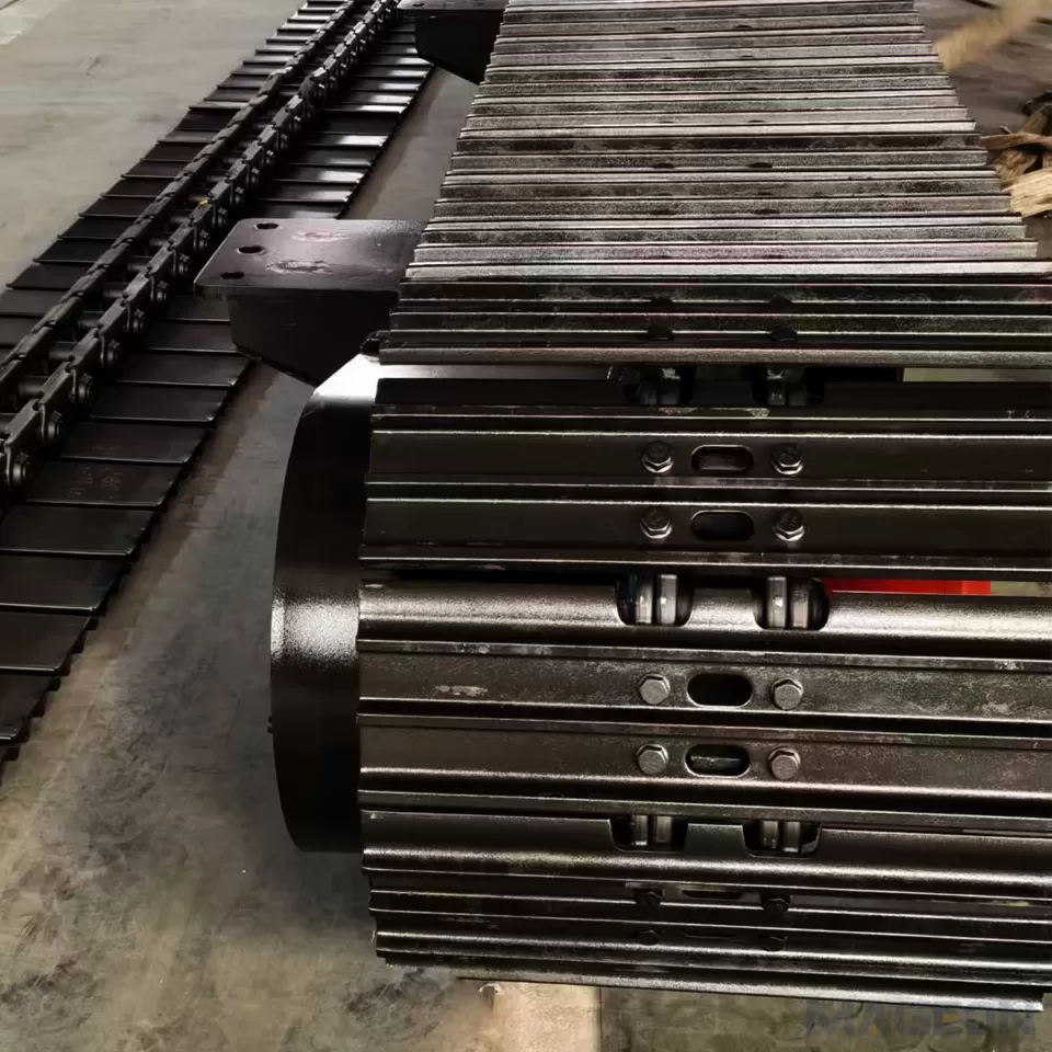
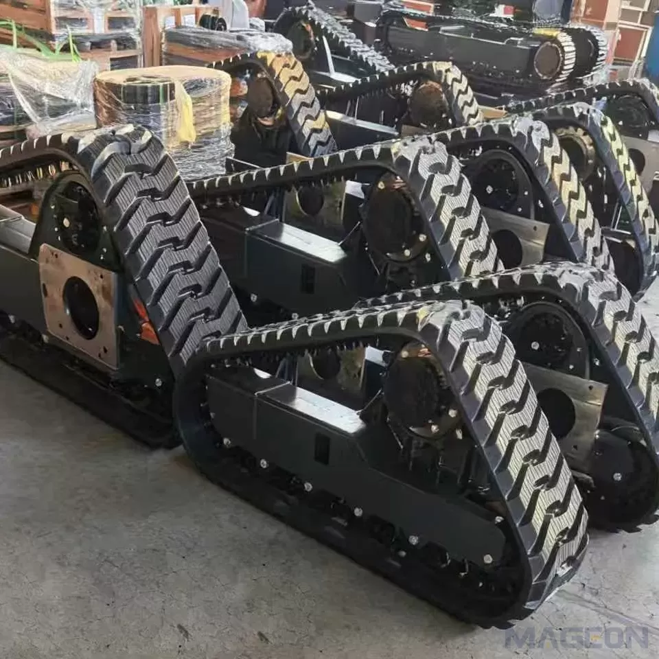
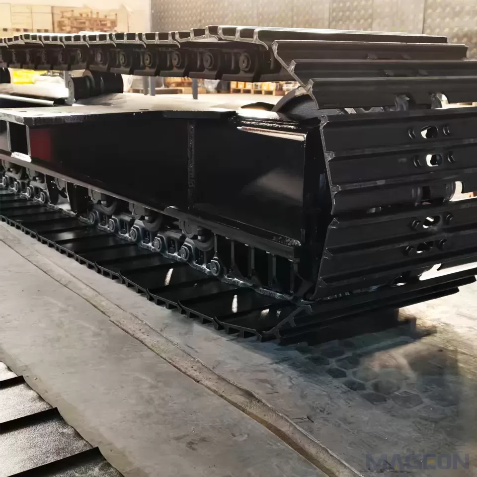
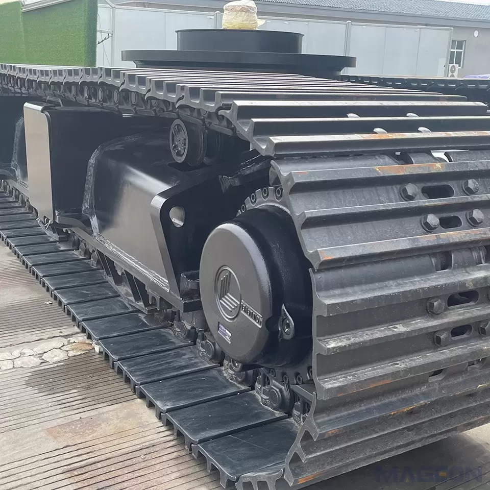
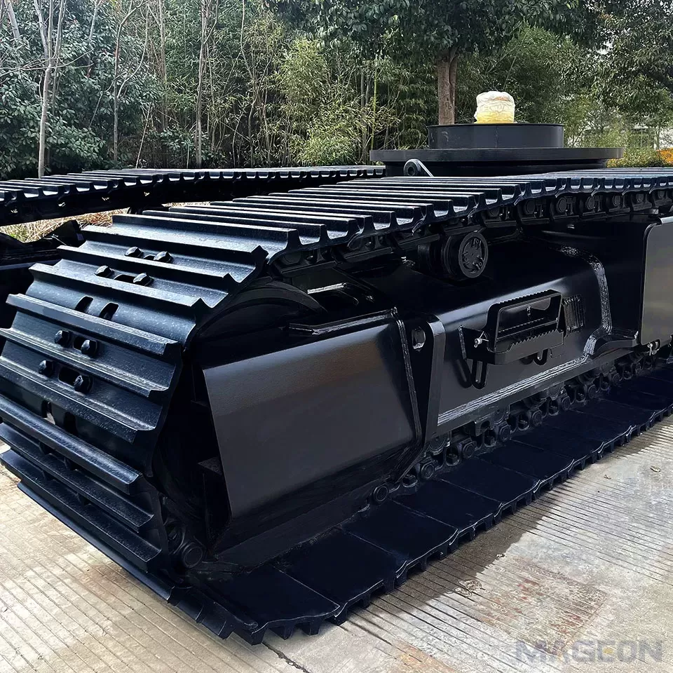
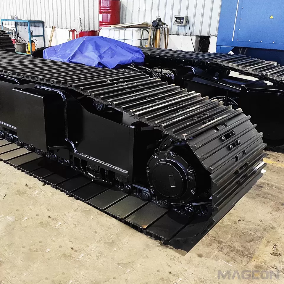
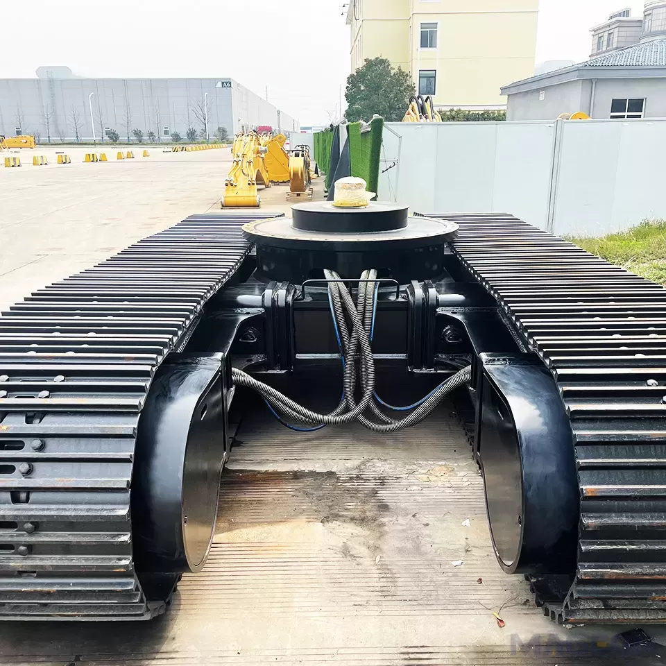
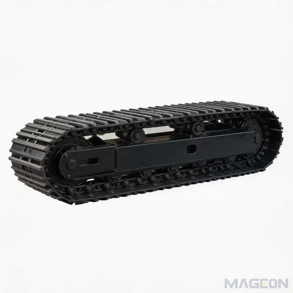
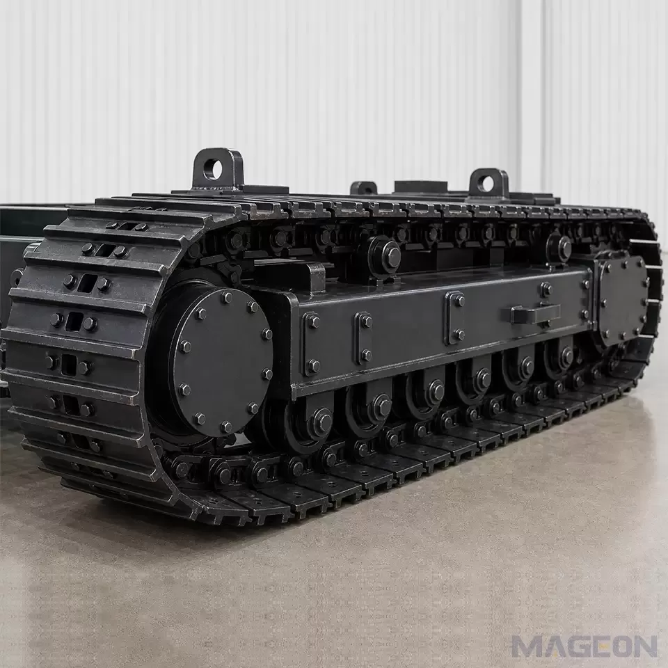
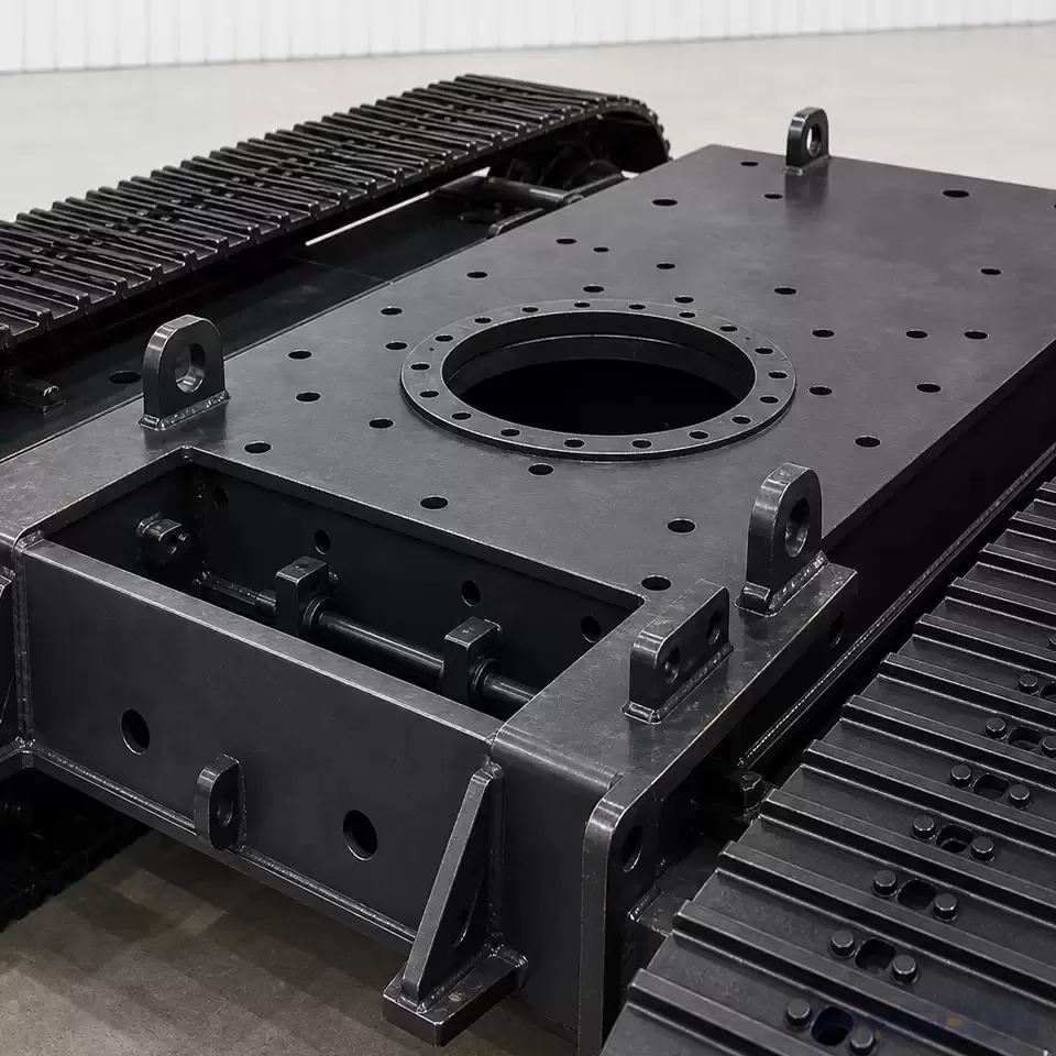
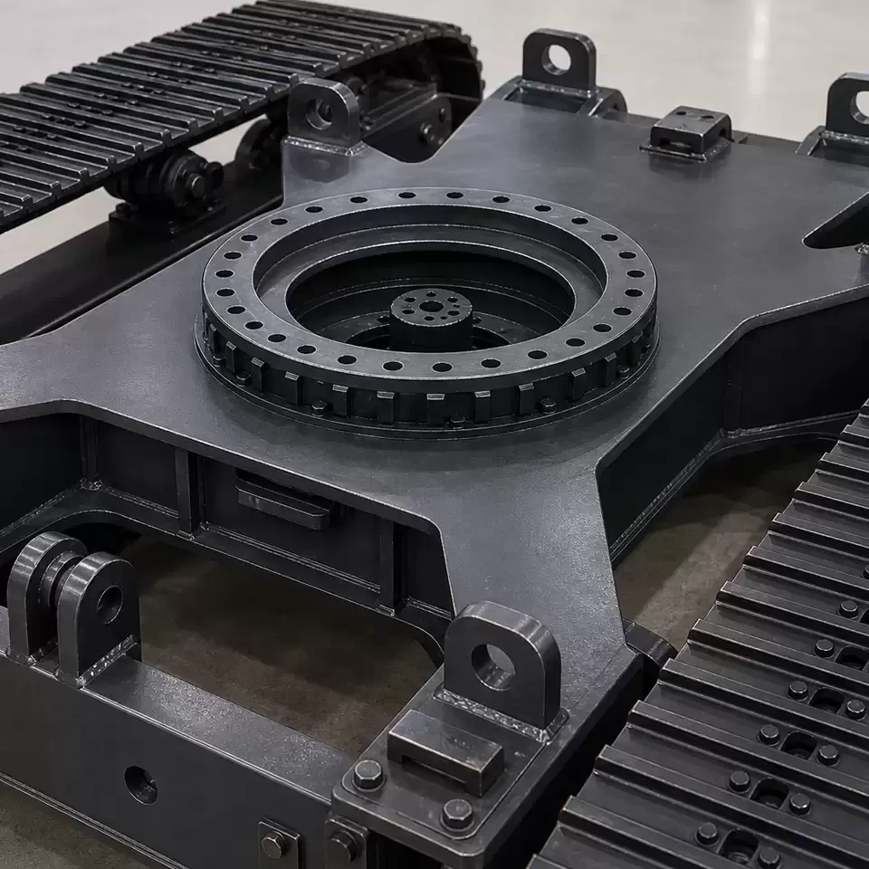
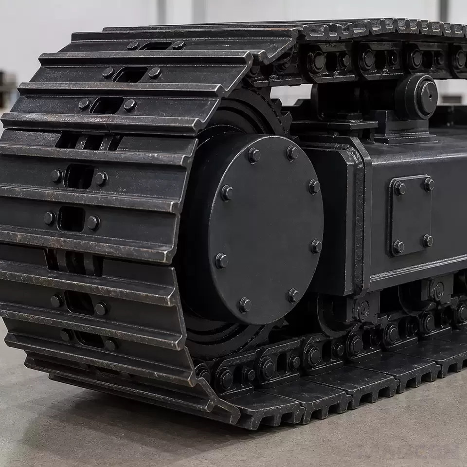
Changing the separation between the two tracks changes the space available between them and can move their outer envelopes. That decision can affect the upper-frame connection, cross-members, drive placement, attachment clearance, hose routing and the space reserved for inspection or component removal. It may also affect whether the complete machine fits a transport envelope, doorway, row spacing or other project-specific access restriction.
A review of crawler undercarriage mounting dimensions should therefore show the track reference axes together with the mounting datums, upper-structure envelope, moving-clearance zones and the maximum permitted machine width. Static clearance alone is insufficient when attachments move, the undercarriage oscillates, or flexible lines need room throughout the duty cycle.
Packaging is a two-way constraint. A narrow transport limit may require changes to track width, component placement or upper-frame layout; reducing gauge without checking turning and stability can simply move the problem.
How Track Gauge Enters a Skid-Steer Turning Decision
A skid-steered crawler turns by creating different motions at the left and right tracks. In an ideal kinematic relationship, turning radius is connected to both track gauge and the difference between the track velocities. A 2024 tracked-vehicle turning model published in Discover Applied Sciences uses track gauge as one model input while also calculating the forces required at the tracks.
This is why track gauge alone cannot predict a real turning radius. The commanded or theoretical track-speed relationship may differ from machine motion because the tracks slip and skid relative to the ground. The drive system must also produce the forces and moments required to overcome resistance during the manoeuvre.
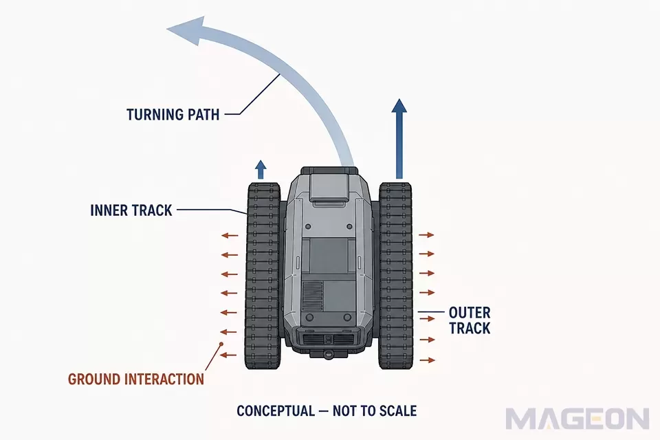
Surface condition changes that resistance. A 2020 soft-terrain turning-resistance study modelled the effects of track sinkage, slip and skid under steady-state conditions. Its assumptions and test context should not be generalized into a universal design rule, but the study supports a critical boundary: geometry-only calculations do not represent every soft-ground turn.
Before accepting a gauge from a turning requirement, the OEM should define:
the required manoeuvres, including gradual turns, minimum-radius turns and pivot or counter-rotation if applicable;
the relevant machine mass and attachment states;
the expected surface, slope, firmness and likelihood of sinkage;
the track contact geometry and planned travel speed;
the available drive, brake and control behaviour for the manoeuvre; and
the acceptance method, such as calculation, simulation or representative machine testing.
The result is a project-specific turning assessment, not a universal statement that one gauge turns “better.”
How Track Gauge Relates to Stability—Without Oversimplifying
Track gauge contributes to the lateral separation of the support regions. For a fixed machine configuration on a defined surface, changing that separation changes the geometry used in a lateral tipping assessment. However, the machine is rarely defined by gauge alone: centre-of-gravity height and lateral position, attachment posture, payload, slope, acceleration, ground deformation and track contact state all affect the assessment.
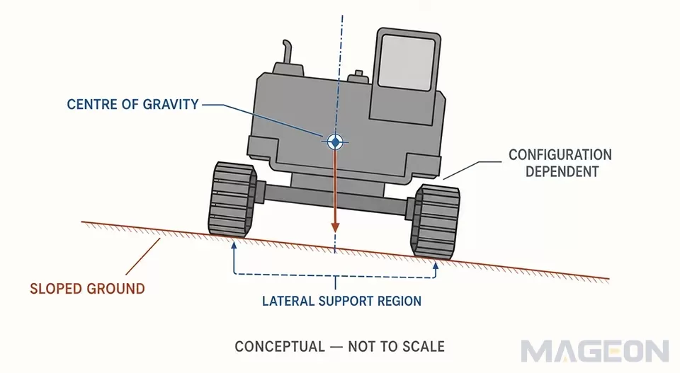
ISO 5005 is especially relevant to this boundary because its scope notes that the centre of gravity of earth-moving machinery depends on the nature and position of attachments or ancillary equipment. ISO 6016 separately provides methods for measuring whole-machine, equipment, attachment and component masses. These standards provide measurement frameworks; citing them does not establish a machine's stability or demonstrate compliance for a particular project.
The OEM should evaluate transport, travel, working and payload configurations because each may move the centre of gravity. A gauge that appears adequate in one static layout may not address another configuration or a dynamic event. Engineers should also distinguish rollover from lateral sliding, which depends on the surface and track-ground interaction.
Average ground contact pressure should not be used as a substitute for this review. ISO 16754 states that its calculated average is for comparing crawler machine models and that actual operating pressure varies with load, centre-of-gravity position, terrain, track shoe type and size, and surface conditions. Changing gauge by itself does not establish a ground-pressure improvement.
Use a Tradeoff Matrix Before Freezing Track Gauge
The following matrix is a scoping tool, not a completed engineering verification. Each row needs project evidence before the gauge is released.
| Possible track-gauge effect | Other required inputs | Verification need | |
|---|---|---|---|
| Packaging | Changes the separation and possible outer envelope of the tracks | Shoe width, component offsets, guards, upper-frame layout, transport limit | Approved envelope and interface drawings in relevant positions |
| Turning | Enters ideal skid-steer geometry and force/moment relationships | Track speeds, contact length, mass distribution, surface, sinkage, slip, drive capability | Model with stated assumptions and representative manoeuvre check |
| Stability | Changes lateral support geometry | Mass, centre of gravity, attachments, payload, slope, contact state, dynamics | Configuration-specific stability assessment and acceptance criteria |
| Ground interaction | May change load distribution only as part of a wider configuration change | Track shoe type and width, contact length, terrain, surface condition |
This matrix exposes cross-effects early. Moving the tracks outward may help one static geometric condition while creating a transport-width conflict or changing skid-steer requirements. The correct decision is the combination that satisfies the defined machine requirements with verifiable margins.
Conclusion
Crawler undercarriage track gauge is a system-level input. It affects packaging, appears in turning relationships and contributes to lateral support geometry, but its real consequences depend on the rest of the machine and its operating environment. Freeze it only after the OEM and relevant suppliers have reviewed the same geometry, mass states, centre-of-gravity data, turning requirements and duty conditions.
For a technical evaluation or inquiry about complete crawler undercarriage assemblies, provide MAGEON with the equipment layout, load and centre-of-gravity information, dimensional constraints, terrain, required manoeuvres and duty conditions. Project-specific engineering confirmation remains necessary before any design is released.
Frequently Asked Questions
What is track gauge on a crawler machine?
Track gauge commonly refers to the lateral distance between the reference axes of the left and right tracks. The drawing should identify those axes and the machine condition used for measurement.
Is track gauge the same as overall machine width?
No. Overall width also depends on track shoe width, frame and component offsets, guards, fasteners and any other feature that forms the outer envelope.
Does a wider track gauge always make a crawler more stable?
No. Gauge contributes to support geometry, but stability also depends on mass distribution, centre-of-gravity position, attachments, payload, slope, surface and dynamic conditions.
Does track gauge determine turning radius?
No. Gauge is one input to ideal skid-steer geometry; track velocities, slip, skid, ground resistance, contact geometry and drive capability affect actual turning behaviour.
Does increasing track gauge reduce ground pressure?
Not by itself. Ground pressure depends on load and the actual track-ground contact conditions, while changing gauge does not automatically increase the supporting contact area.
Which information should an OEM send before confirming track gauge?
Send the layout and width limits, relevant machine masses, centre-of-gravity data, track contact geometry, required manoeuvres, terrain and slope conditions, transport limits and duty cycle. The supplier and OEM can then identify which conclusions require calculation, drawing review or physical validation.
Applicable products:
What OEMs Should Provide for Engineering Evaluation
A custom crawler undercarriage specification should record the proposed gauge together with its reference axes and the configurations in which it applies. The project package should also include:
general arrangement and interface drawings with datums, track centre lines and outer-envelope limits;
machine mass by relevant configuration, including attachments and payload states;
centre-of-gravity coordinates or the approved method and responsibility for determining them;
track shoe width, ground-contact length and other contact-geometry definitions;
required travel and turning manoeuvres, speeds, control modes and acceptance criteria;
terrain, surface strength, slope, obstacles and expected sinkage or slip conditions; and
transport, access, maintenance and duty-cycle constraints.
This is part of the broader technical information required before undercarriage design, not a replacement for the full design-input package. If any decision-critical dimension, load state or centre-of-gravity value is unknown, the gauge should remain open for engineering confirmation rather than being filled with a typical value.
Please leave your customization requirements, and we will contact you as soon as possible!
Leave your requirements, we'll get back to you within 24 hours.