How to choose a steel rail chassis for remote agricultural equipment?
Introduction
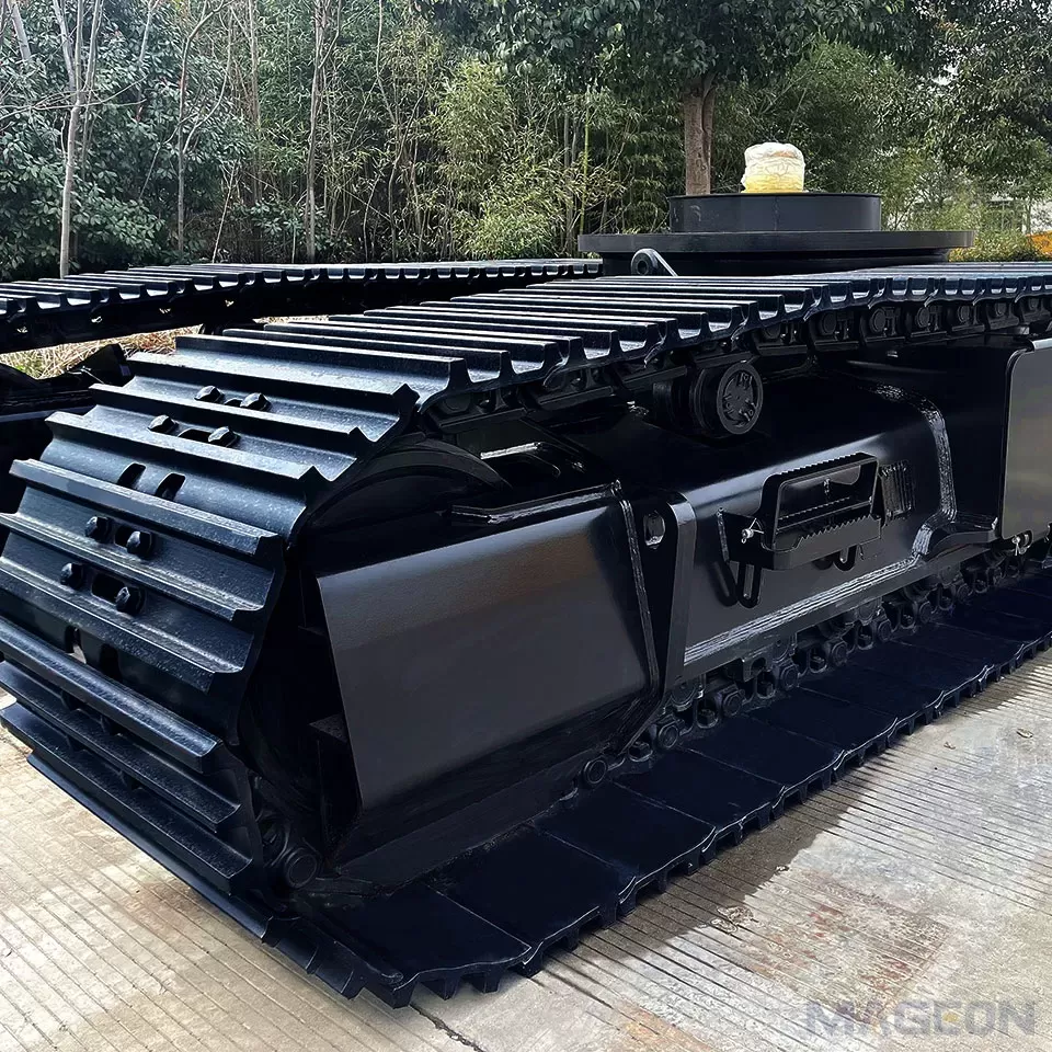
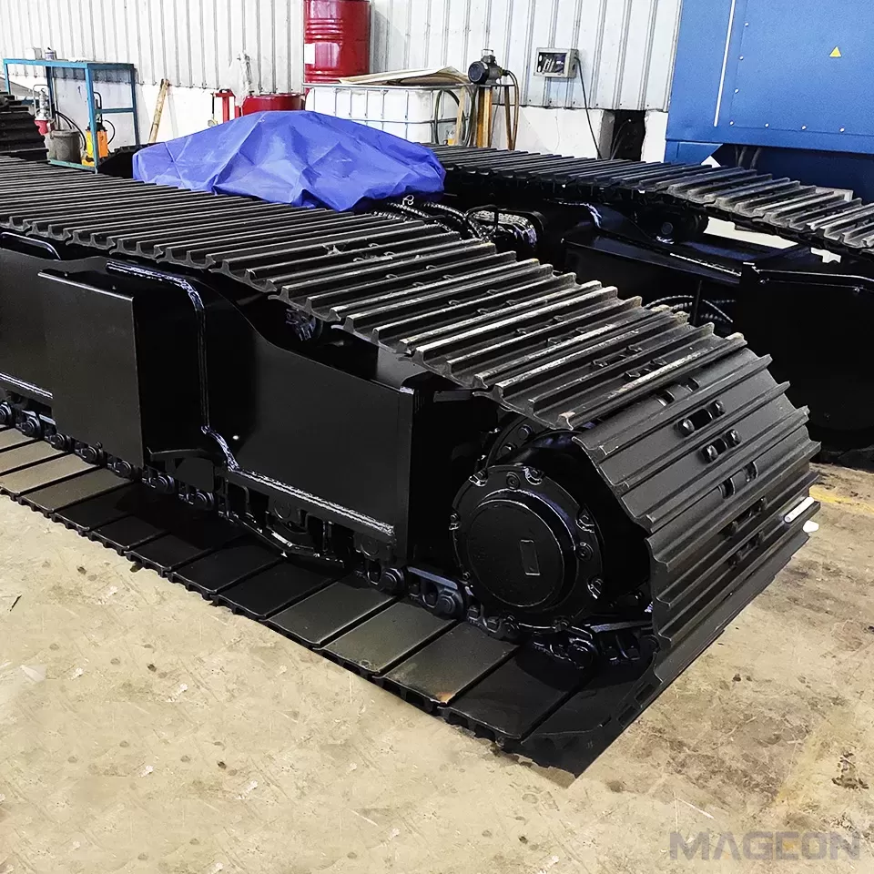
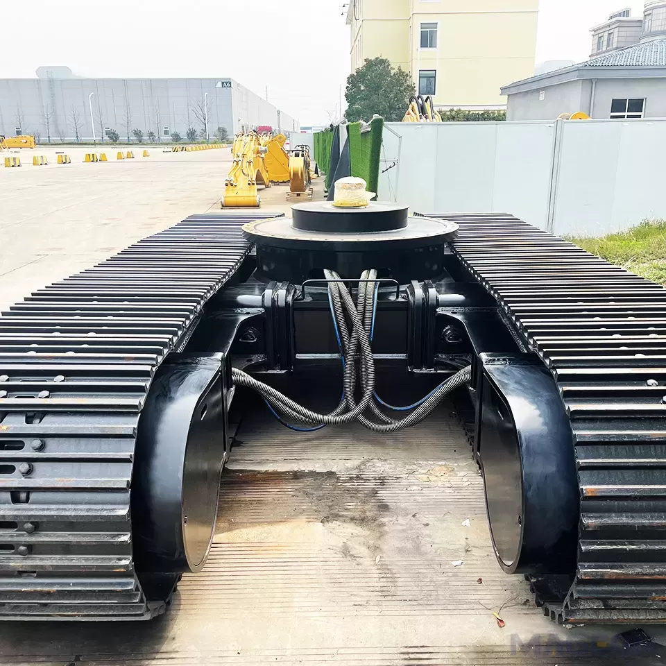
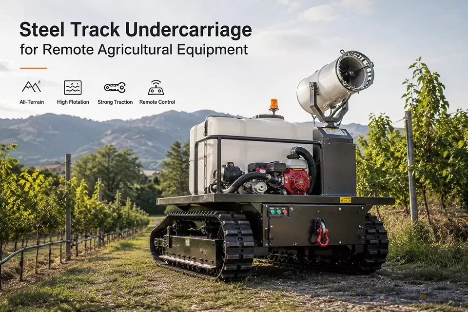
A steeltrack undercarriage is more than a mobile base. It combines the structural frame, track system, travel drives, braking components, hydraulic circuits, and machine interface into one platform. When remote control is added, the undercarriage must also respond predictably to electronic commands while maintaining safe travel, steering, stopping, and parking behavior.
This combination is increasingly relevant to agricultural transport vehicles, orchard equipment, material-handling platforms, sprayers, mowing machines, inspection units, and other machines that operate on mud, loose soil, broken ground, narrow paths, or slopes.
However, there is no universal tracked chassis for every project. A system designed for level farm transport may not provide the same stability, braking control, or ground clearance required on a hillside. Selection must therefore begin with the actual terrain, load, machine layout, operating speed, hydraulic source, and control method.
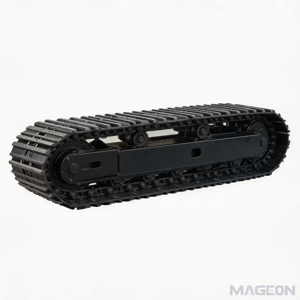
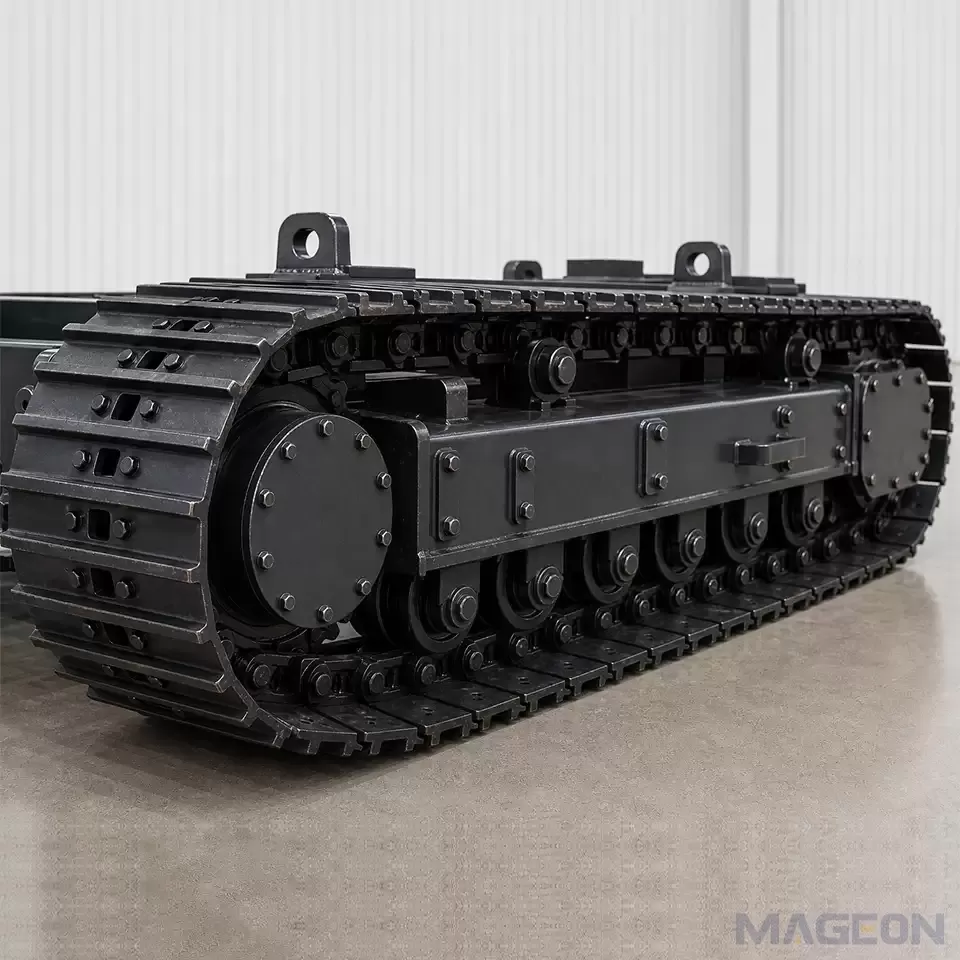
What Is a Steel Track Undercarriage Assembly?
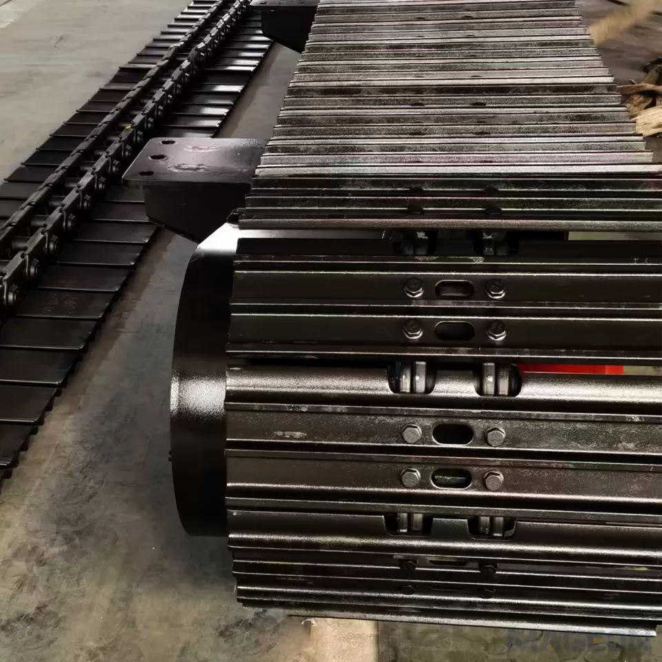
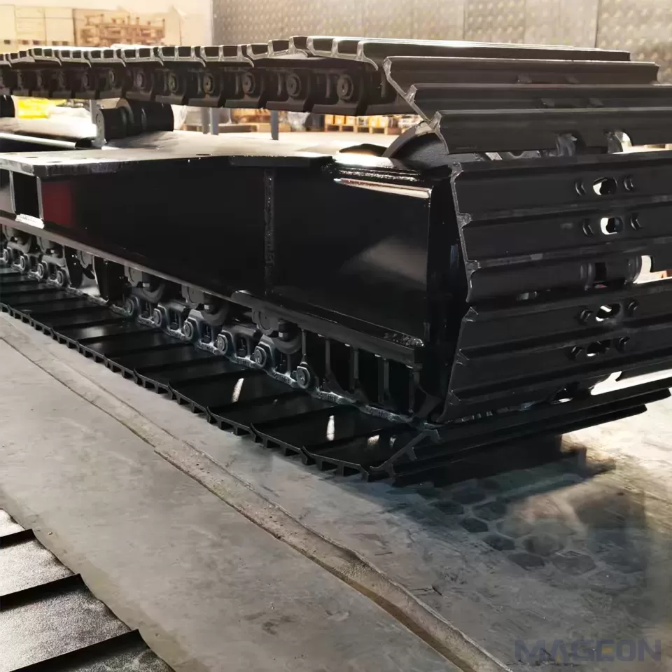
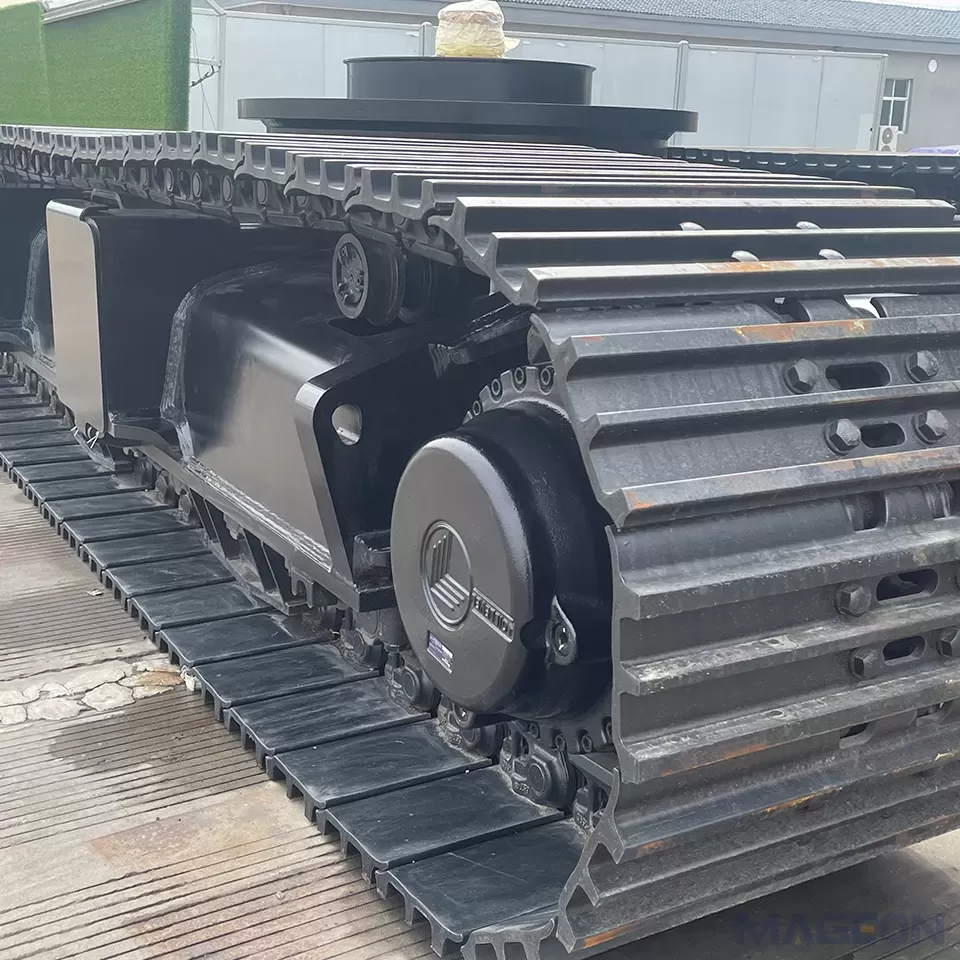
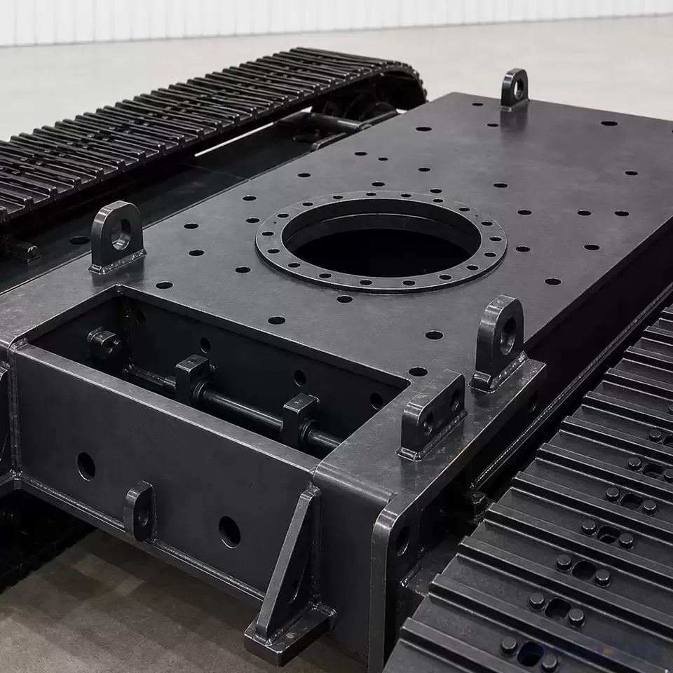
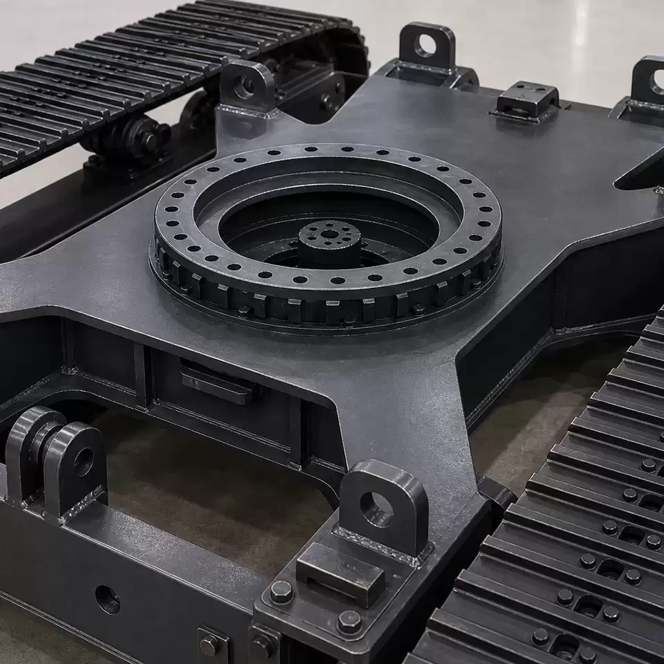
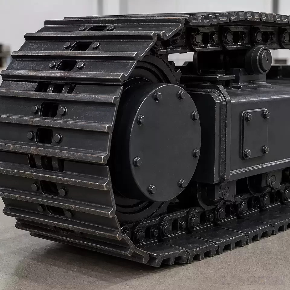
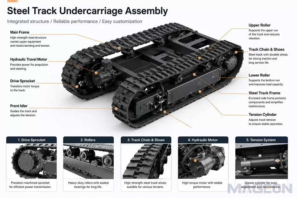
A complete undercarriage assembly normally integrates several functional groups.
| Main Function | Project Information Required | |
|---|---|---|
| Main frame | Carries the upper equipment and resists bending and torsion | Equipment weight, payload, center of gravity, mounting points, and frame dimensions |
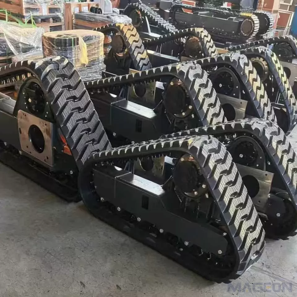
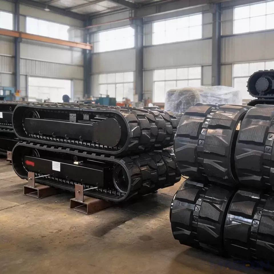
| Track chains and shoes | Transfer drive force and create ground contact | Track width, pitch, shoe pattern, ground conditions, and required flotation |
| Rollers and idlers | Support, guide, and tension the track | Track geometry, roller arrangement, alignment, and service access |
| Drive sprockets | Transfer motor torque to the tracks | Track pitch, sprocket profile, motor interface, and required travel force |
| Hydraulic travel motors | Provide propulsion and steering | Machine mass, slope, speed, torque, pressure, flow, and duty cycle |
| Braking system | Controls stopping and parking | Maximum operating slope, loaded mass, stopping requirement, and fail-safe behavior |
| Hydraulic control system | Regulates direction, speed, and motor flow | Pump data, valve type, pressure, flow, filtration, and cooling conditions |
| Remote-control system | Converts operator commands into machine movement | Control distance, response requirement, emergency stop, signal-loss behavior, and feedback data |
| Upper-machine interface | Connects the customer’s equipment to the chassis |
The frame and track system form the mechanical foundation. Hydraulic motors rotate the drive sprockets, causing the left and right tracks to move. Steering is achieved by changing the relative direction or speed of the two tracks. The remote-control system sends commands to the control valves or electronic actuators, while the braking and safety circuits determine how the machine behaves when the operator stops, releases the control, or loses communication.
Why Working Conditions Must Come First
Two tracked platforms with similar dimensions can behave very differently if their loads, centers of gravity, track widths, drive ratios, or control strategies are not the same. The following conditions should be defined before selecting components.
Level Agricultural Transport
On firm and relatively level ground, buyers usually prioritize travel efficiency, maneuverability, payload, and energy consumption. A compact chassis may be suitable, but the frame, motor sizing, braking, and thermal capacity must still match the loaded machine rather than the empty platform.
Orchard and Narrow-Path Operation
Orchard machines often require a small turning radius, controlled steering, and limited overall width. Tree rows, drainage channels, roots, and soft soil may restrict available space. Track width and machine width must be considered together because wider tracks improve flotation but can reduce access.
Mud, Soft Soil, and Wet Fields
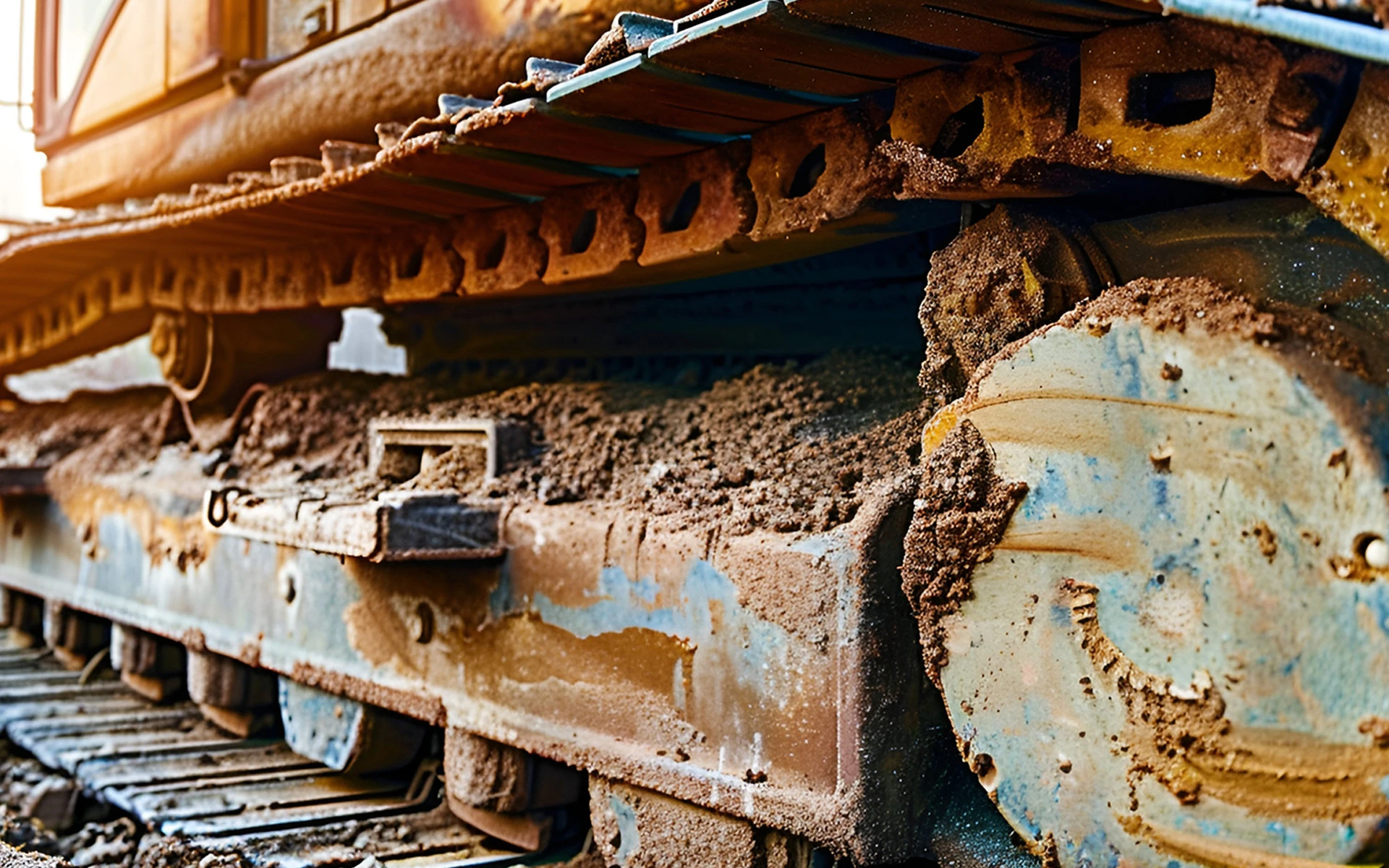
Soft ground increases the importance of ground-contact area, track-shoe design, cleaning clearance, and material packing. A wider track may reduce ground pressure, but excessive width can increase turning resistance and loads on track components. The correct solution balances flotation, overall width, steering load, and structural durability.
Uneven or Sloped Terrain
Slope work requires more than additional motor torque. The complete machine must be evaluated for center-of-gravity position, lateral and longitudinal stability, braking, parking, track grip, downhill speed control, and remote-command behavior. A chassis should not be approved for slope operation only because it can climb an unloaded test surface.
Core Selection Factors
1. Total Operating Mass and Payload
Provide the chassis mass, upper-machine mass, maximum payload, liquids, attachments, batteries, tanks, and any load that changes during operation. Motor torque, frame strength, roller loading, track selection, and braking performance depend on the complete operating configuration.
2. Center of Gravity
The horizontal and vertical center of gravity affects slope stability, turning behavior, and track loading. Buyers should provide the upper-machine layout rather than only an overall weight. Tall tanks, offset implements, lifting mechanisms, and moving payloads can shift the center of gravity during work.
3. Track Width and Ground Contact
Track width should be selected according to soil condition, required flotation, machine width, turning resistance, and component loading. Wider is not automatically safer. On firm ground, unnecessary width may increase steering resistance. On soft ground, insufficient contact area can increase sinkage and loss of mobility.
4. Travel Speed and Drive Torque
High speed and high tractive effort require different drive ratios. If the project needs both controlled low-speed work and faster transfer travel, a two-speed motor or another verified drive strategy may be considered. The supplier needs the required speed range, loaded slope, wheel or sprocket geometry, hydraulic pressure, and available flow to evaluate the travel drive.
5. Braking and Parking
The braking system must hold the complete machine on the specified slope and control stopping under load. For remote equipment, safe-state behavior is essential: the project should define what happens when the operator releases the travel command, activates emergency stop, or loses signal.
6. Ground Clearance and Obstacle Crossing
Ground clearance must match crop rows, stones, ruts, drainage channels, and other obstacles. Raising the frame can improve clearance but may also raise the center of gravity. Clearance, stability, and upper-machine layout must therefore be reviewed together.
Application Guide
| Main Requirement | Undercarriage Focus | Control Focus | |
|---|---|---|---|
| Farm material transport | Payload and predictable travel | Frame capacity, motor sizing, and service access | Smooth acceleration and reliable stopping |
| Orchard transport or spraying | Narrow access and small turning radius | Controlled overall width and suitable track contact | Precise low-speed steering |
| Wet-field operation | Flotation and resistance to packing | Track width, shoe design, and cleaning clearance | Controlled torque without excessive track spin |
| Hillside mowing or transport | Stability and braking | Center of gravity, track grip, and parking brake | Signal-loss stop and downhill speed control |
| Remote inspection platform | Low-speed positioning and equipment interface | Compact frame and mounting accuracy | Low-latency control and status feedback |
| Special agricultural machine | Integration with customer equipment | Custom mounting, hose routing, and weight distribution |
How Hydraulic and Remote-Control Systems Work Together
An electric-hydraulic remote-control system uses electronic commands to operate hydraulic valves or proportional actuators. The hydraulic system still provides travel force, but direction and speed are controlled through an electrical command layer. This makes remote operation possible and can support functions such as proportional steering, speed-mode selection, emergency stop, and status monitoring.
A reliable system requires coordination between the controller, receiver, valve, pump, motors, brakes, sensors, and wiring. Remote range alone does not prove control quality. The project should also evaluate command response under load, steering consistency, behavior near obstacles, resistance to electromagnetic interference, enclosure protection, and signal-loss response.
The following safety logic should be defined before production:
What happens when the remote signal is interrupted?
Does the travel command automatically return to neutral?
How is the parking brake applied?
Is there a local emergency-stop device on the machine?
Can the operator recover or move the machine safely after a control fault?
Which operating values are displayed or recorded?
These functions must be verified on the complete machine because controller behavior can change with hydraulic load, oil temperature, power supply, and valve response.
Pre-Delivery Verification
A drawing review alone is not sufficient for a remote-controlled tracked platform. The acceptance plan should match the actual operating risk.
| What Should Be Checked | |
|---|---|
| Drawing and interface review | Overall dimensions, mounting points, track alignment, service access, hoses, wiring, and center of gravity |
| Static load check | Frame deformation, roller loading, mounting stability, and ground clearance under load |
| Travel test | Forward and reverse travel, steering, low-speed control, speed modes, and abnormal noise |
| Braking and parking test | Loaded stopping, parking on the specified slope, emergency stop, and brake release behavior |
| Remote-control test | Command response, operating range, interference resistance, signal-loss action, and local emergency stop |
| Hydraulic test | Pressure, flow, temperature, leakage, filtration, motor response, and relief-valve behavior |
| Terrain test |
Test conditions, machine load, ground condition, and acceptance limits should be documented. A no-load factory demonstration cannot replace a test that represents the customer’s actual application.
aintenance Considerations
Daily inspection should cover track tension, loose fasteners, shoe damage, roller and idler leakage, hydraulic hoses, electrical connectors, emergency-stop devices, and material packed around the tracks. Remote-control equipment should also be checked for battery condition, receiver status, antenna damage, and consistent command response.
Track tension and hydraulic settings must follow the approved machine documentation. Excessive tension increases component load, while insufficient tension can cause poor engagement or derailment. Any repeated steering difference between the left and right tracks should be investigated rather than corrected only through remote-control calibration.
Conclusion
Selecting a steel track undercarriage for remote agricultural equipment requires coordinated mechanical, hydraulic, electrical, and safety decisions. The key inputs are operating mass, payload, center of gravity, terrain, slope, track contact, speed, drive torque, braking, hydraulic supply, and remote-control behavior.
For a MAGEON project enquiry, provide the complete operating configuration and interface drawings before requesting a final solution. Accurate application data is more reliable than choosing a chassis by appearance, nominal load, or track width alone.
Frequently Asked Questions
1. What is the difference between electric-hydraulic remote control and hydraulic control?
Hydraulic control uses valves and hydraulic pressure to operate the travel motors. Electric-hydraulic remote control adds an electronic command system that operates the valves or proportional actuators from a remote controller. The hydraulic circuit still provides the drive force. Selection depends on the required operating distance, steering precision, feedback, emergency-stop logic, signal-loss behavior, and available electrical power.
2. What equipment can use a steel track undercarriage?
Steel track undercarriages can support agricultural transport vehicles, orchard machines, sprayers, mowing platforms, remote inspection units, material-handling equipment, and other special tracked machinery. Compatibility cannot be confirmed from equipment type alone. The chassis must match operating weight, payload, center of gravity, dimensions, hydraulic supply, mounting interface, ground conditions, speed, braking, and control requirements.
3. How should track width be selected?
Track width should provide sufficient ground contact for the soil without creating unnecessary overall width or steering resistance. Soft ground may require greater contact area, while orchards and narrow paths may limit machine width. Buyers should provide operating mass, ground conditions, required clearance, turning space, and transport restrictions. Wider tracks should not be selected without checking their effect on turning loads and stability.
4. Is a higher-torque travel motor always better?
No. Motor selection must match hydraulic pressure, flow, displacement, drive ratio, sprocket geometry, machine mass, speed, slope, and duty cycle. An oversized motor may not deliver the required speed or may operate inefficiently with the available pump. A complete travel calculation should balance low-speed tractive effort, steering behavior, transfer speed, thermal load, and braking requirements.
5. What data is needed to calculate slope capability?
Provide total operating mass, payload, center-of-gravity position, track dimensions, ground surface, required travel direction, desired speed, motor and drive data, and braking configuration. Slope capability should be assessed for climbing, descending, parking, lateral stability, and turning. An unloaded climbing test does not prove that the complete machine is safe under its maximum working configuration.
6. What should happen if the remote-control signal is lost?
The required safe-state behavior must be defined during system design. A typical project may require travel commands to return to neutral, hydraulic flow to stop, and the parking brake to apply. The exact sequence depends on the control architecture and risk assessment. Signal-loss behavior, emergency stop, restart conditions, and local recovery controls should be verified on the complete loaded machine.
7. Can the upper equipment be installed directly on the track frame?
Only when the mounting interface and load distribution have been verified. The supplier needs the bolt pattern, equipment dimensions, operating weight, center of gravity, dynamic loads, and service-access requirements. Concentrated loads or an offset center of gravity may require reinforcement or a different frame layout. Hose, cable, battery, tank, and maintenance-clearance requirements should also be included in the installation drawing.
8. How long does a custom undercarriage project take?
The schedule depends on whether the project uses an existing platform or requires a new frame, hydraulic calculation, control integration, tooling, testing, or certification. A reliable delivery estimate requires confirmed drawings, operating data, quantities, and acceptance criteria. Design changes after production begins can extend the schedule, so interface and performance requirements should be approved before manufacturing.
9. Can worn steel tracks be replaced separately?
Track shoes, chains, rollers, idlers, sprockets, and related parts may be serviceable separately, depending on the chassis design and wear condition. Before replacing one part, inspect the components that contact it. A new chain operating with a severely worn sprocket—or a new sprocket engaging a worn chain—can create poor contact and accelerated wear. Use the approved specifications and service limits.
10. What should be checked before the machine is shipped?
Confirm dimensions, mounting interfaces, track alignment, hydraulic pressure and flow, leakage, travel direction, steering, braking, emergency stop, signal-loss response, remote range, loaded operation, and the agreed terrain or slope tests. Inspection records should identify the test load and acceptance limits. The delivered configuration should match the approved drawings, component list, wiring, hose routing, and control functions.
Applicable products:
Information Required for a Custom Project
For a MAGEON steel track undercarriage enquiry, prepare:
Complete machine type and intended task
Empty weight, operating weight, and maximum payload
Upper-machine dimensions and center-of-gravity information
Required chassis length, width, and ground clearance
Desired track width and ground-contact length
Maximum travel speed and low-speed control requirement
Maximum working slope and ground conditions
Available hydraulic pressure, flow, and oil type
Motor, pump, valve, and brake preferences if already defined
Required remote-control distance and operating functions
Emergency-stop and signal-loss requirements
Mounting drawings, hose routes, cable routes, and connector locations
Required quantity and destination market
Providing these inputs early reduces repeated design changes and prevents the chassis from being selected only by its external dimensions.
Please leave your customization requirements, and we will contact you as soon as possible!
Leave your requirements, we'll get back to you within 24 hours.