Crawler Undercarriages for Solar Farm Pile Driving: Repetitive Positioning and Ground Pressure
Solar farm pile driving is a high-cycle, short-travel duty: the machine advances a few metres, stops, drives one pile, and repeats hundreds of times per day. That pattern makes ground pressure, low-speed positioning accuracy, brake holding and thermal stability more important than top travel speed. An undercarriage specified like a general drilling rig chassis will usually be too heavy for soft ground, too coarse at crawl speed, and will wear its track chain in one short section.
This article sets out the parameters that actually govern the choice for a photovoltaic piling rig, with a worked ground-pressure calculation and a specification checklist for OEMs building machines for utility-scale solar sites.
1. How the Solar Piling Duty Cycle Differs
The distinction matters because component sizing follows the load spectrum, not the machine's nameplate. A piling rig that drives a pile every 60–90 seconds accumulates more start-stop events in a week than a general-purpose drill accumulates in a month.
| Duty characteristic | General drilling / excavation | Solar farm pile driving | Effect on undercarriage specification |
|---|---|---|---|
| Travel per cycle | Tens to hundreds of metres | Typically 2–4 m between pile rows | Track chain wears in a short repeating zone; specify chain quality and rotation policy |
| Speed profile | Sustained travel | Frequent accelerate / decelerate / hold | Brake holding torque, cooling and low-speed controllability dominate |
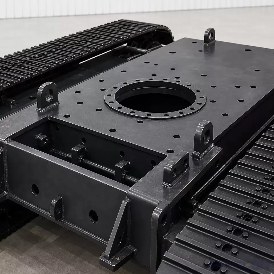
| Tool reaction | Variable, often vertical | Repetitive axial impact or vibratory reaction | Mast load path into the cross-member must be fatigue-rated, not just strength-rated |
| Ground | Prepared platform, often compacted | Untreated topsoil, sand, reclaimed or agricultural land | Ground pressure and flotation usually set the track width, not the machine mass |
| Positioning tolerance | Centimetres to decimetres | Pile position tolerance often a few centimetres | Crawl-speed control, drive backlash and slew bearing play become functional requirements |
| Site gradient | Usually levelled | Rolling terrain; hillside arrays can exceed 15° | Tip-over margin, traction on slope and parking brake rating need explicit checks |
2. Calculate Ground Pressure Rather Than Assuming It
Nominal ground bearing pressure is the machine's working mass divided by the contact area of the two tracks:
p = (m × g) / (2 × L × B), where m is working mass in kg, g = 9.81 m/s², L is the track contact length on the ground and B is the shoe width, both in metres. The result is in pascals; divide by 1,000 for kPa.
Worked example: a 9,000 kg piling rig with 2.4 m contact length and 400 mm shoes gives p = (9,000 × 9.81) / (2 × 2.4 × 0.40) = 88,290 / 1.92 ≈ 46 kPa. Widening the shoes to 500 mm drops this to about 37 kPa. For soft agricultural topsoil, a target in the 30–45 kPa range is commonly used as a starting point, but the binding limit should come from the site's soil bearing capacity, not from a catalogue figure.
Two corrections are frequently missed. First, nominal pressure assumes uniform contact; with the mast extended and the hammer forward, the real pressure distribution is strongly trapezoidal and the peak under the front rollers can be two or three times the nominal value. Second, working mass must include the pile magazine, fuel, counterweight and the reaction force from the piling tool — not just the bare machine. Ask the supplier which load case their quoted ground pressure refers to.
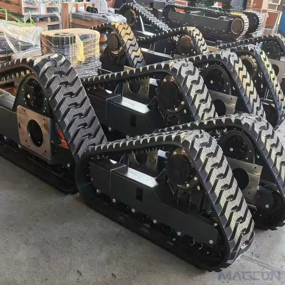
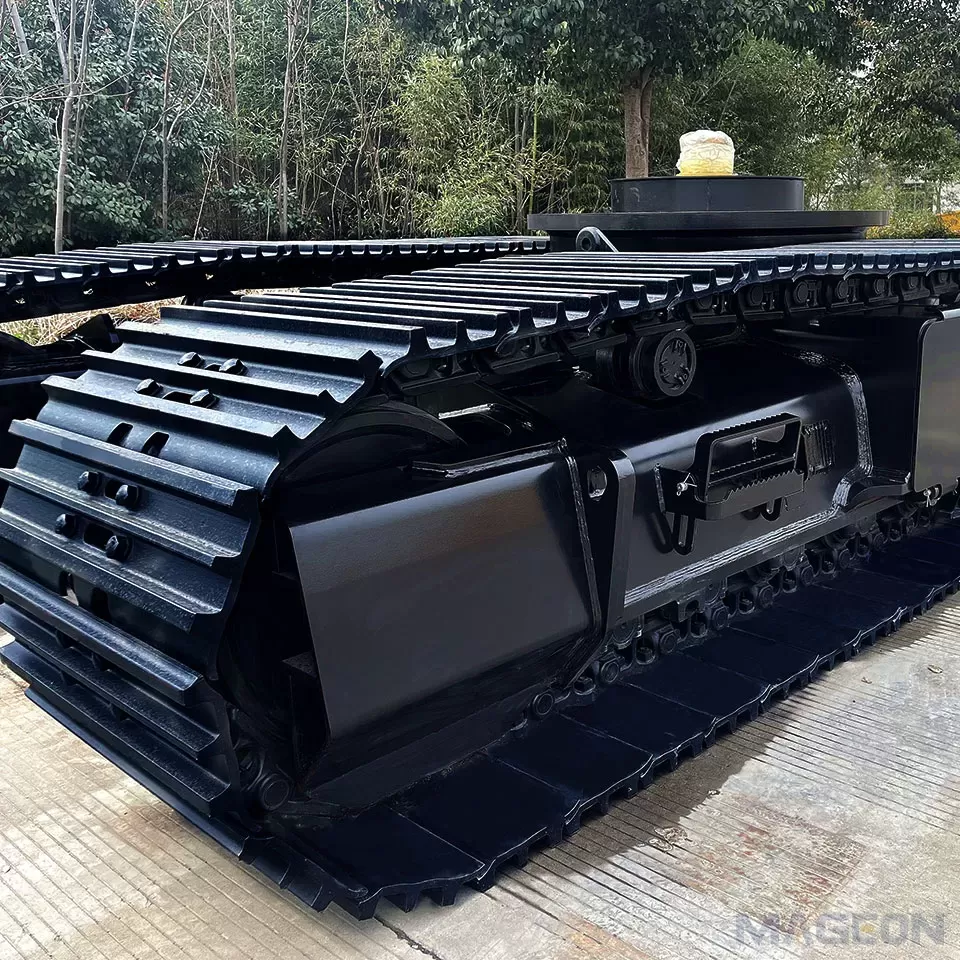
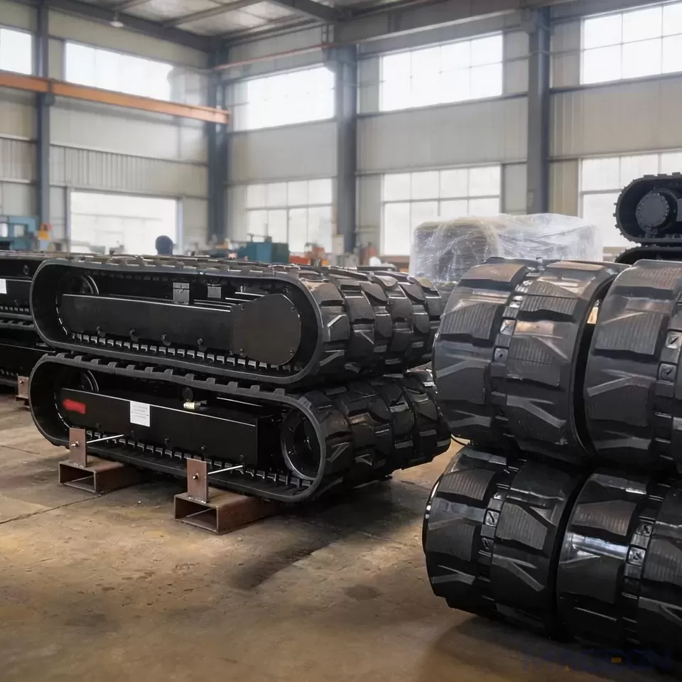
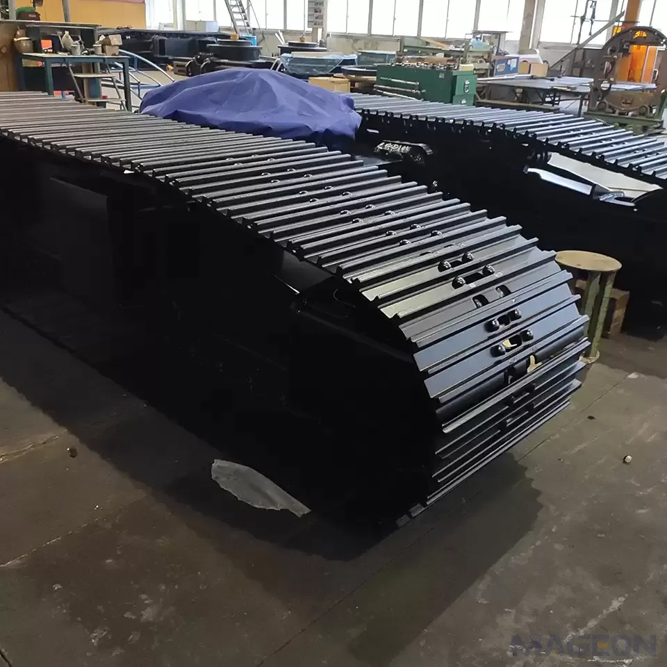
For very soft sites, a rubber track undercarriage or a wider steel shoe spread over a longer frame is often more effective than simply reducing machine mass, and it protects prepared ground and access roads between array blocks.
3. What the Chassis Actually Controls in Repetitive Positioning
Pile position accuracy is a system property, but several contributors sit inside the undercarriage:
- Low-speed controllability — proportional valve resolution and motor displacement determine whether the operator can creep 50 mm or overshoots by 300 mm. High reduction ratios with small-displacement motors can be jerky at crawl speed.
- Drive backlash — accumulated clearance in the final drive gearing and chain engagement appears as a dead band each time travel direction reverses.
- Track slip on slope — repeated stop/start on a cross-slope causes a small lateral drift per cycle that compounds along the row.
- Parking brake holding — a negative multi-disc brake sized for transport only may creep under vibratory piling reaction.
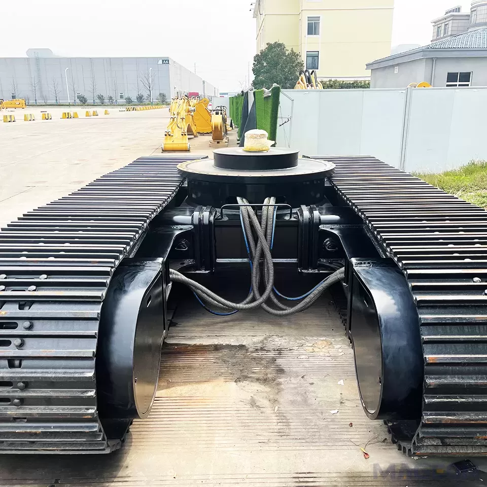
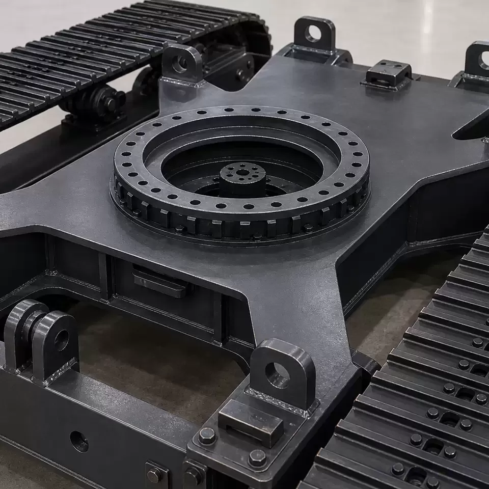
- Slew bearing play — where the upper structure rotates, bearing clearance and mounting-face flatness set the angular repeatability of the mast.
For machines that integrate machine control or GPS guidance, share the expected closed-loop behaviour with the undercarriage supplier at the specification stage. The hydraulic drilling rig undercarriage drive needs a predictable speed-to-command relationship; a drive tuned only for manual lever control will fight an automated positioning loop.
4. Slope, Row Geometry and Stability
Utility-scale sites follow the terrain, so a chassis may work across a side slope for an entire shift. Verify three separate limits: the traction limit (available coefficient of friction times normal load), the tip-over margin (CG height and track gauge against the design gradient), and the brake holding torque with the mast raised. These are independent — a machine can have ample traction and still be limited by stability.
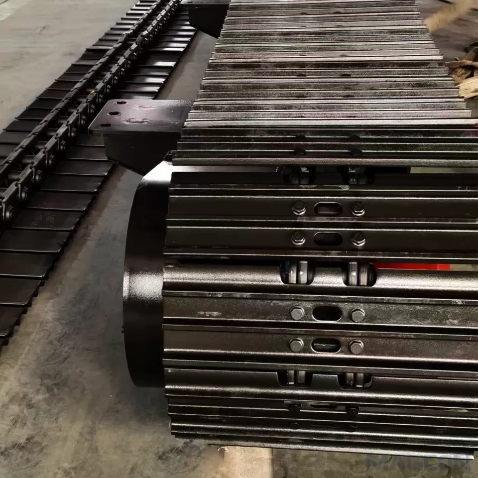
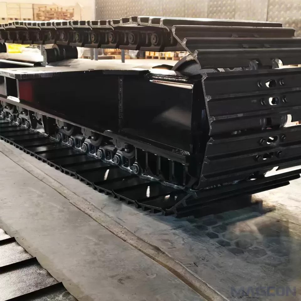
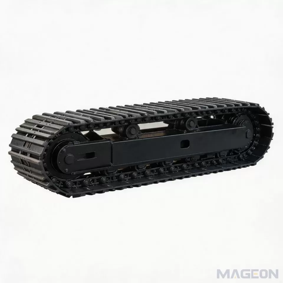
Track gauge is the lever here. A wider gauge improves cross-slope stability and lets the machine keep the mast vertical on undulating ground, but it increases transport width. A telescopic crawler undercarriage resolves the conflict by extending for work and retracting for transport or for narrow access between completed rows. On sites with tight row spacing, confirm the retracted width against the actual array pitch before finalising the design.
5. Wear Pattern and Service Planning
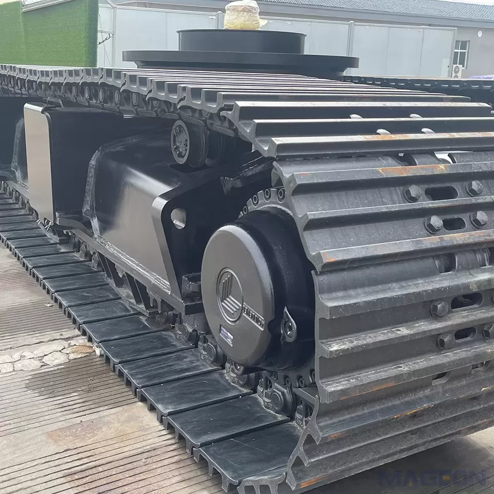
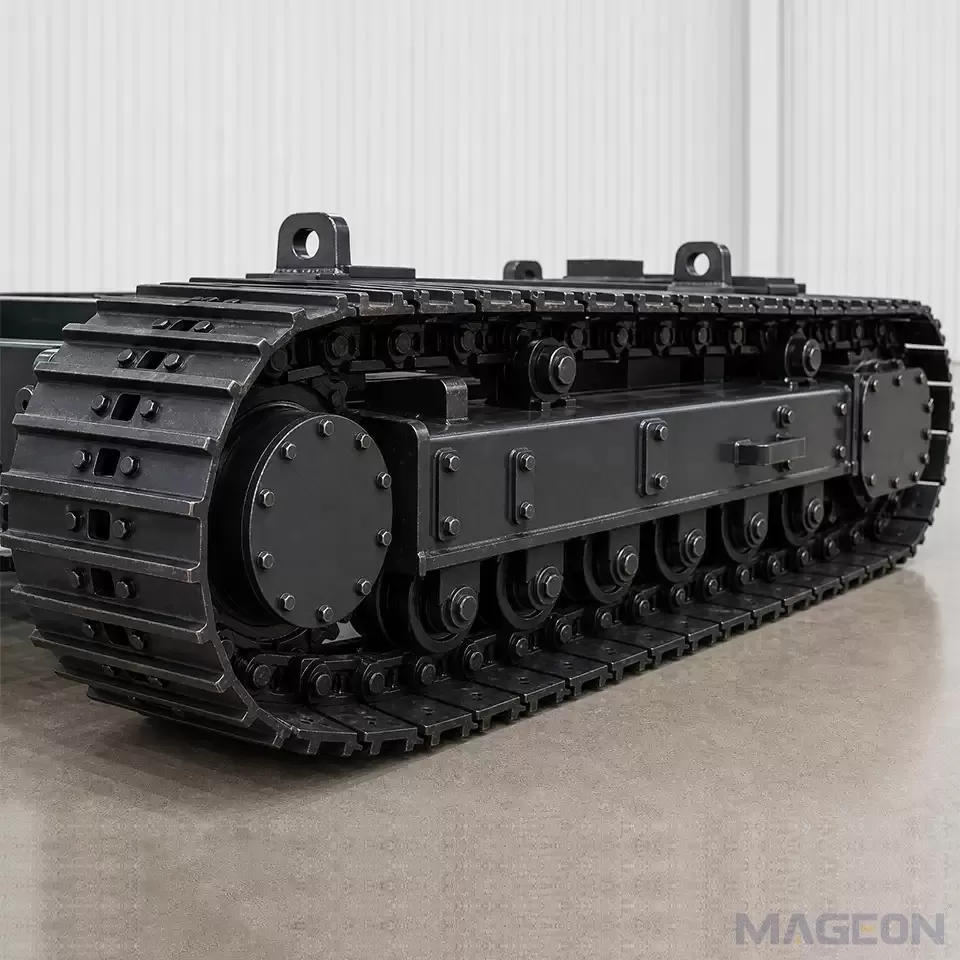
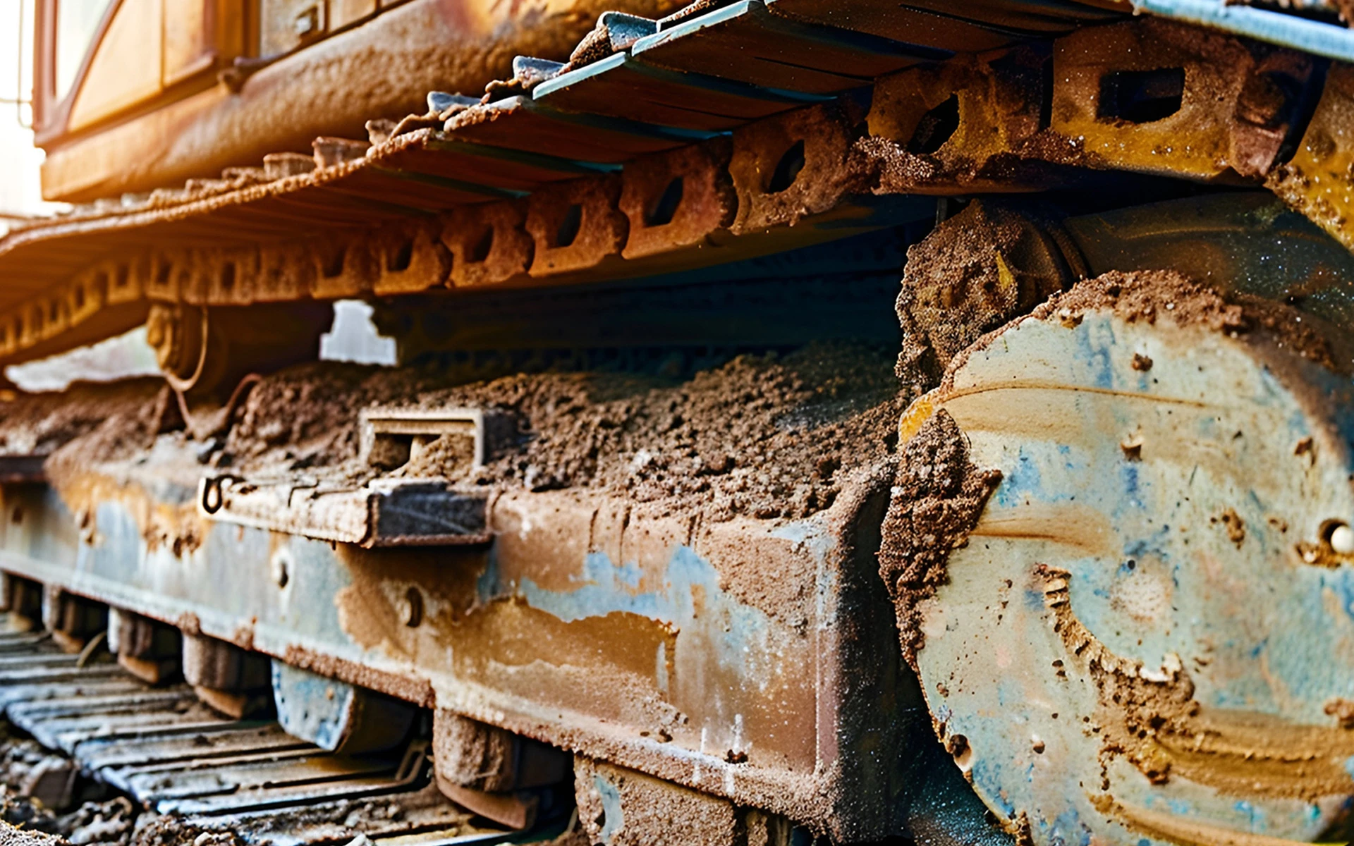
Because travel distance per cycle is short, the same few chain links repeatedly pass under the drive sprocket and the front idler. Expect localised wear: check pin/bush clearance and sprocket tooth profile in the high-cycle zone rather than relying on a whole-chain average. Sealed and lubricated chains reduce the rate substantially, and a documented chain rotation or inspection interval is cheaper than an unplanned stop in the middle of a field.
Dust and abrasive sand are the second wear driver. Specify effective mud and debris relief around the sprocket, accessible tensioning adjusters, and a cleaning routine that does not require dismantling the track frame. Keep rollers, idlers and sprockets as separately orderable wear items with a stated expected interval for the site conditions, so the fleet operator can stock the right parts.
6. Solar Piling Undercarriage Specification Checklist
Every item below should be stated as a number with units, not an adjective:
- Working mass in the worst configuration, including pile magazine, counterweight and tool reaction
- Ground bearing pressure, both nominal and peak under the extended-mast load case
- Track gauge extended and retracted, contact length, shoe width and shoe profile
- Maximum working gradient in both travel and cross-slope directions, with the applicable stability standard
- Minimum controllable creep speed and the maximum positioning overshoot at that speed
- Parking brake holding torque and brake release procedure for towing
- Hydraulic supply flow and pressure, and the thermal balance over a continuous shift
- Wear-part list with inspection intervals for the actual soil abrasivity
Frequently Asked Questions
What ground pressure should a solar piling rig target?
There is no universal number; it depends on the site's soil bearing capacity. As an engineering starting point, 30–45 kPa nominal is commonly used for unprepared agricultural or sandy ground, with the peak pressure under the extended mast checked separately.
Is a telescopic undercarriage worth it for solar farms?
It is when the site combines cross-slope work with narrow row spacing or road-transport width limits. The machine can run wide for stability and retract for transport or tight access; the added complexity is justified by the working envelope, not by the specification alone.
Why does the track chain wear so quickly on piling rigs?
Short repeated travel concentrates sliding and load on a limited number of links, and vibratory reaction adds fretting at the pin/bush interface. Sealed lubricated chains plus a rotation and inspection plan address both mechanisms.
Related Products and Next Step
MAGEON supplies drilling rig undercarriages, rotary drilling rig chassis, telescopic crawler undercarriages and custom tracked chassis for piling and photovoltaic equipment. Send the working mass, the site soil bearing value, the row pitch and the maximum gradient; we will return a ground-pressure calculation and a track geometry proposal before the OEM/ODM design package is released.
Please leave your customization requirements, and we will contact you as soon as possible!
Leave your requirements, we'll get back to you within 24 hours.