What are the key technical requirements for steel track undercarriages matched with rotary drilling rigs?
Matching a Chassis to a Rotary Drilling Rig
A rotary drilling rig imposes a load pattern that is unusual for a crawler undercarriage: a continuous downward thrust, plus a reaction torque from the rotating drill head, plus a tall mast that moves the centre of gravity forward. A chassis designed for excavation will feel this and may show it. These are the requirements we design against.
The Four Requirements That Drive the Design
| Requirement | What it means | Design response |
|---|---|---|
| Downforce capacity | Rig weight plus the maximum feed force must be carried by the track | Ground bearing pressure below 0.3 bar on soft ground; wide track shoes |
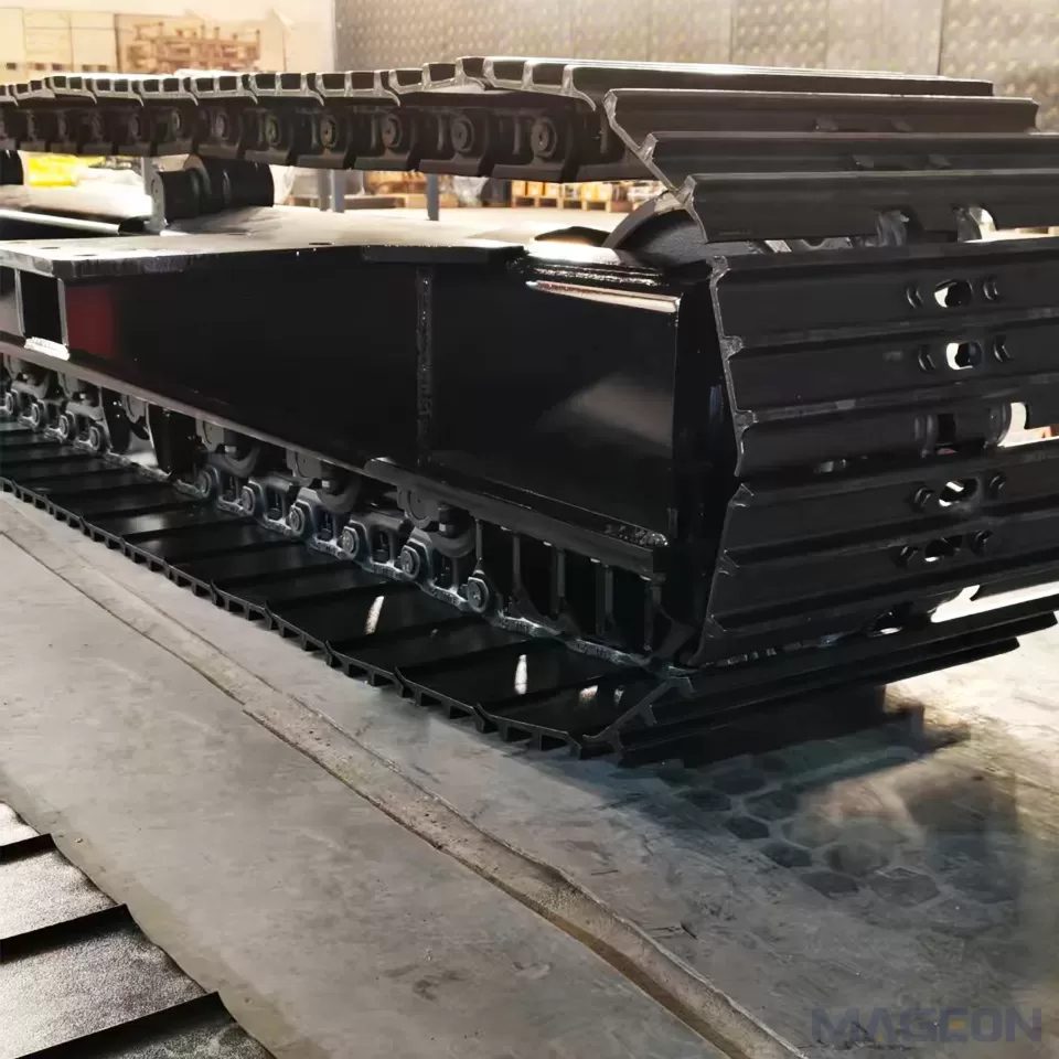
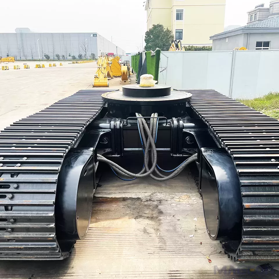
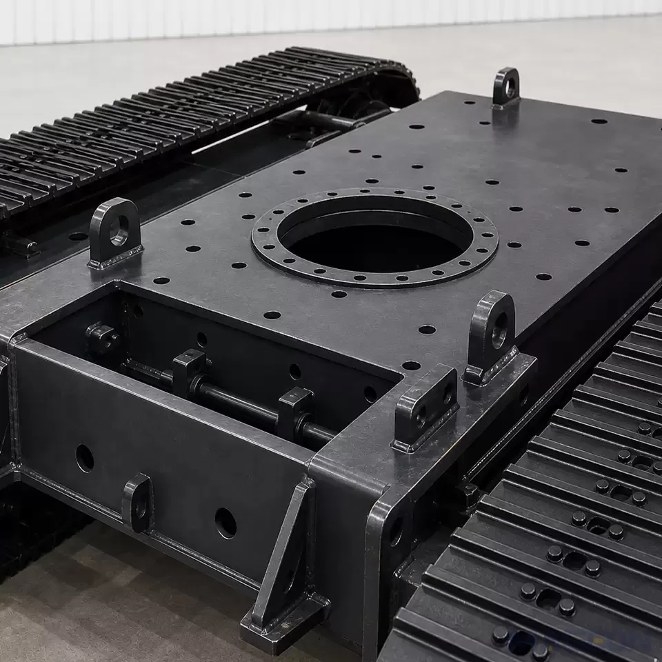
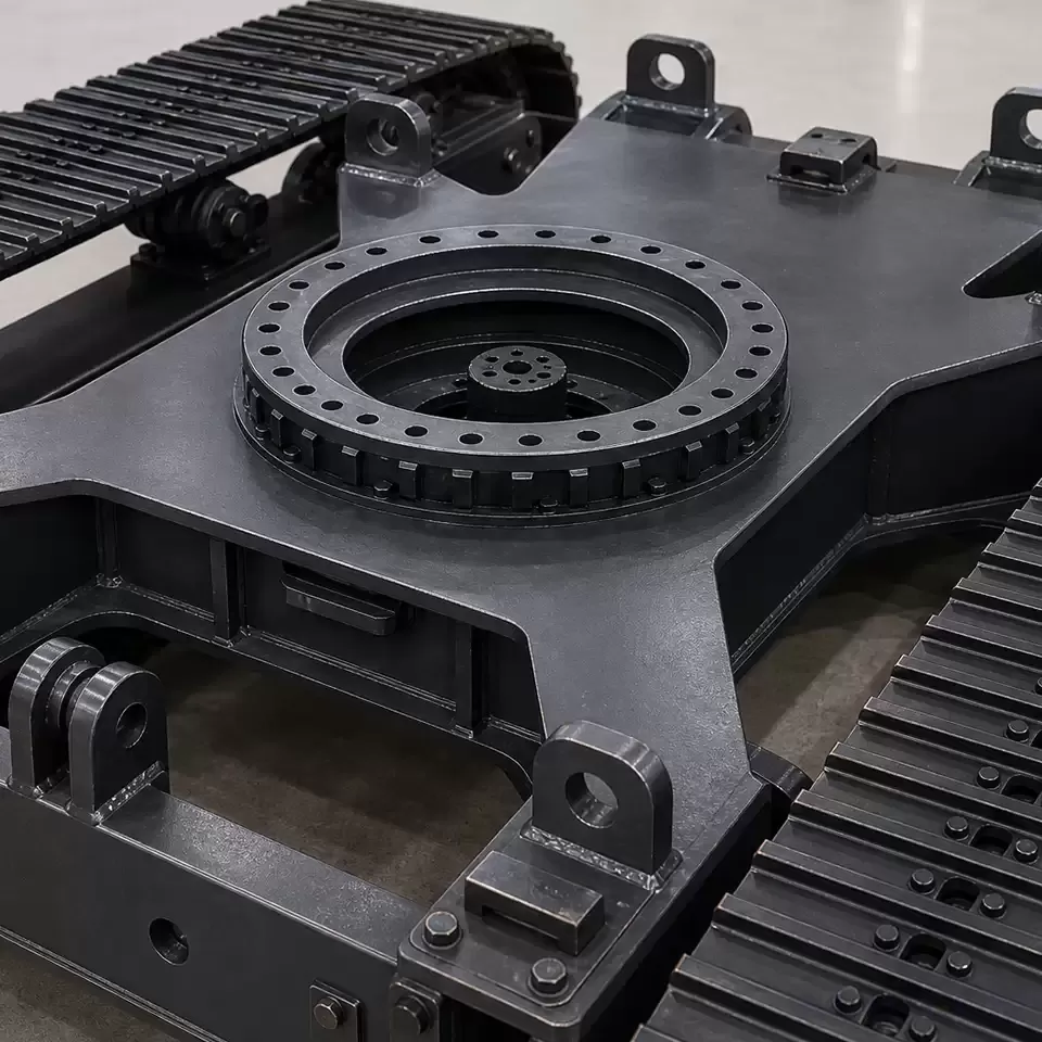
| Reaction torque | The drill head torque reacts against the chassis | Diagonal bracing in the frame weldment, and a rigid connection between the track frame and the upper structure |
| Stability with mast forward | A tall mast with feed force shifts the load forward | Track length and the front/rear roller distribution sized so the tipping point is not reached at maximum feed |
| Dynamic response | Continuous vibration from rotating and feeding | Stress-relieved frame welds, and the sprocket engagement designed to absorb the cyclic load rather than the roller mounts |
Key Technical Parameters to Confirm
- Rig gross weight including mast, deck, and the full feed force
- Maximum drilling torque and how it is reacted - this drives the frame bracing requirement
- Feed force range and the feed speed, because impact load at bit break-in matters
- Ground bearing capacity at the site, typically 0.1-0.3 bar for soft ground
- Working envelope - the horizontal reach of the mast, which sets the tipping constraint
- Track width required to keep ground pressure within the soil limit
- Transport configuration - whether the chassis must be retracted for road transport
Four-Wheels-One-Track as Used on Drills
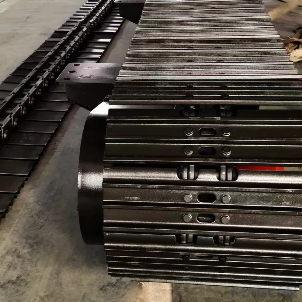
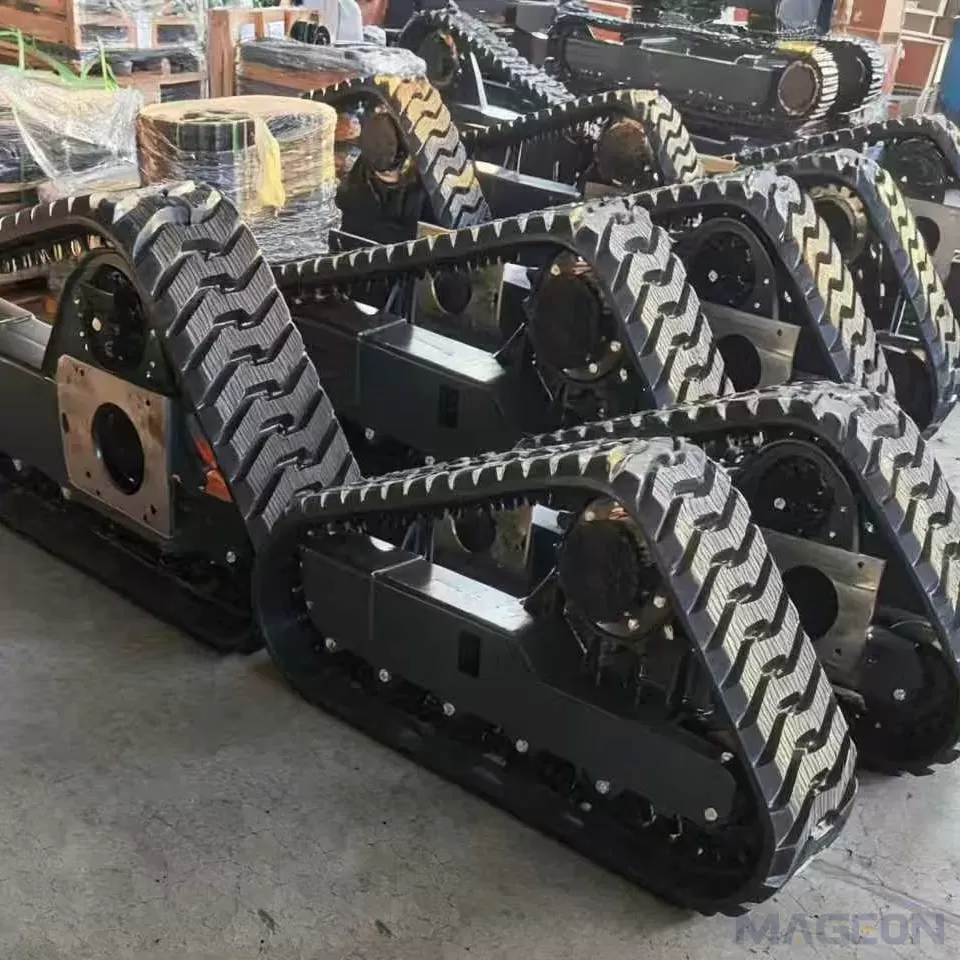
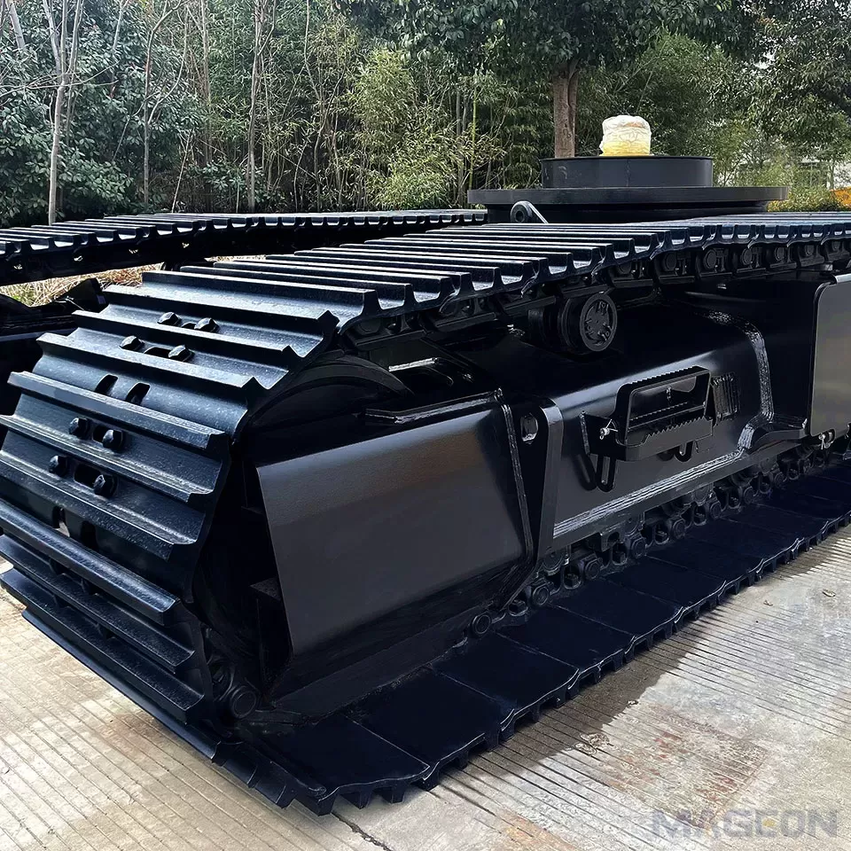
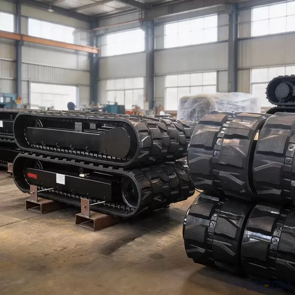
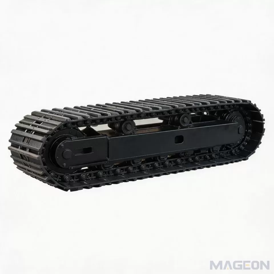
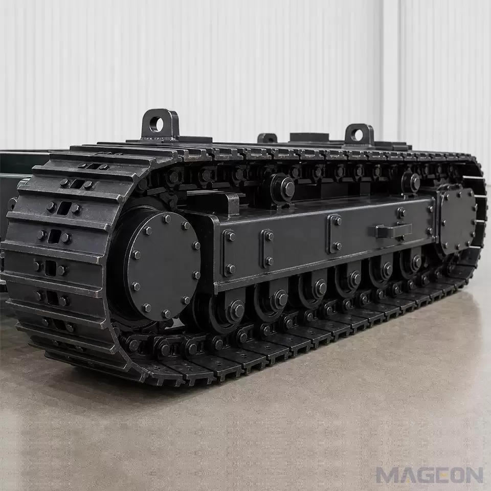
Most modern rotary drilling rigs use a mixed arrangement: a crawler track at the rear carrying the drive and the main load, and rubber wheels at the front controlling the feed reaction. The engineering focus sits in the transition zone. The wheel line must resist the drilling reaction without transmitting shock into the track section, and the articulation between the two must accommodate the mast's movement.
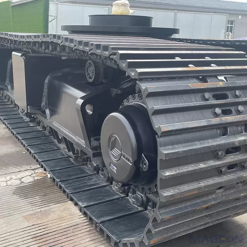
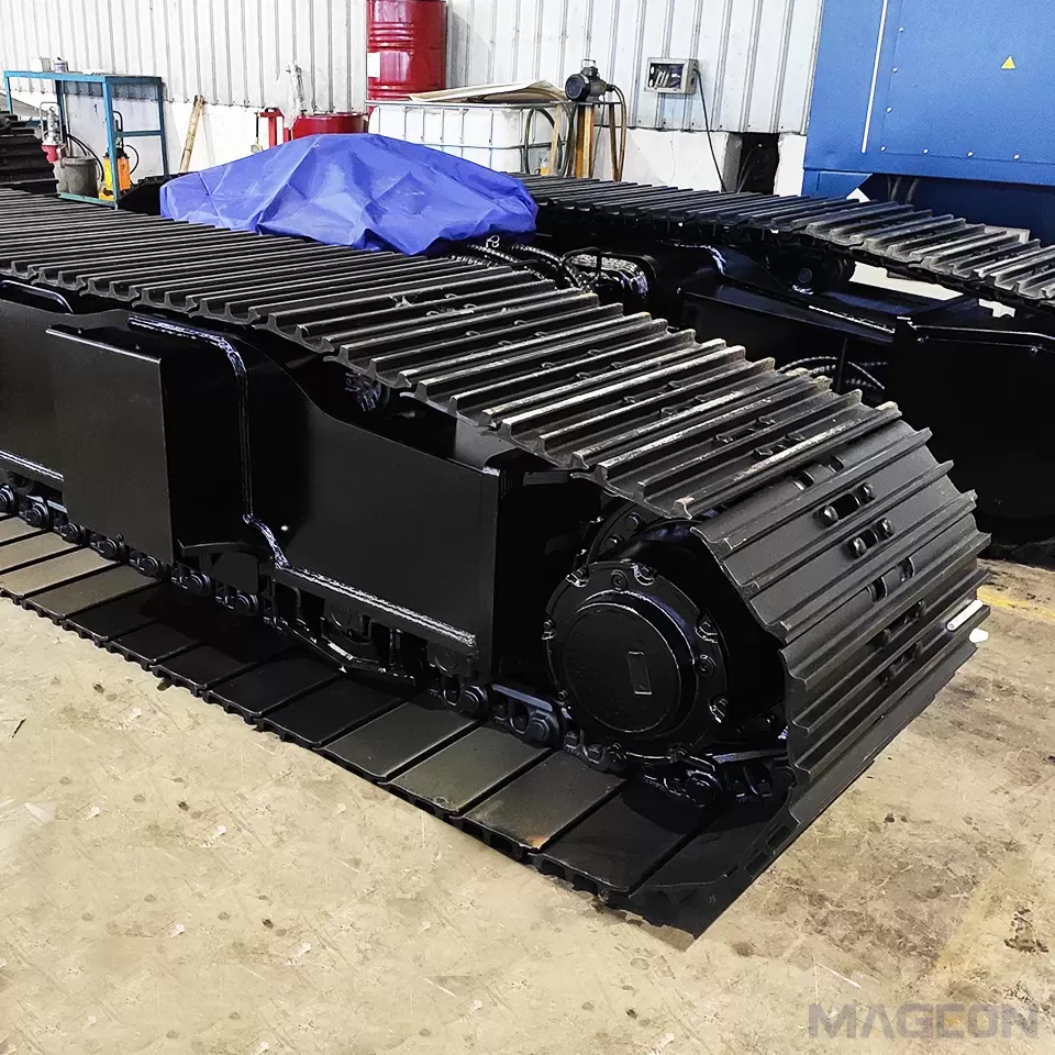
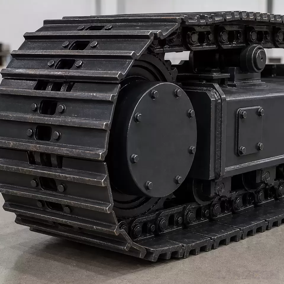
In this configuration, the drive sprocket sits at the front of the track section close to the walking beam, which shortens the load path from the mast into the chain. The chain itself sees a higher cyclic component than in an excavator application, so the heat treatment and the pin fit are specified higher than a general-duty chassis would require.
Ground Pressure Calculation
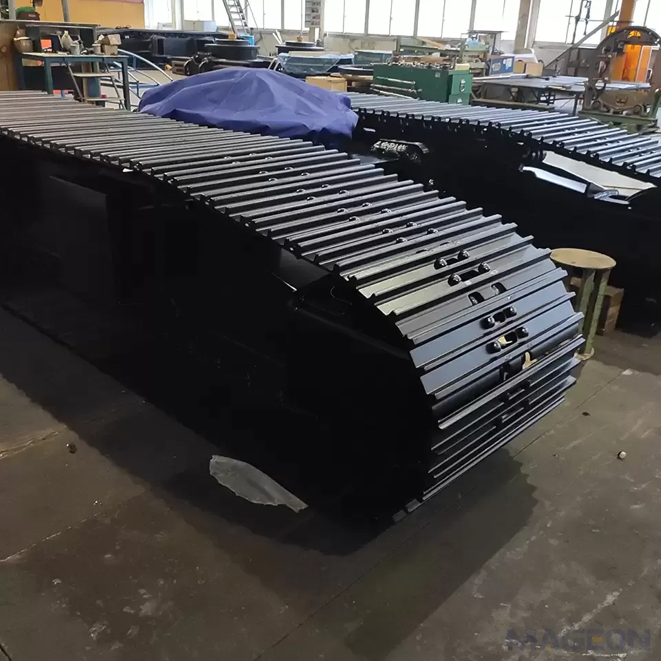
The check we run first is ground bearing pressure. The contact area is the track shoe area, and for a typical 600mm shoe on a rig of 45T, the calculation gives roughly 0.28 bar - which is at the upper limit for soft clay and above it for peat or recently filled ground. If the calculation comes out too high, there are three levers, in order of preference: widen the track, lengthen it to increase the contact length, or reduce the machine weight by reviewing the counterweight. Increasing the shoe width is usually the cheapest of the three, and a shoe pattern with a wider grouser plate is often better than simply making the shoe wider.
Verification and Testing
Every rig chassis is load tested before dispatch, with the test load set above the rated machine weight to include the feed force contribution. For rigs we also run a static deflection check on the frame at the mast mounting point, because excessive deflection there shows up as drill bit wander and shortened bit life, which the operator experiences as poor drilling performance even when the chassis is structurally sound. The deflection figure and the recommended grouser specification for the expected ground condition are included in the documentation.
Send us the rig weight, drilling torque, feed force, and the expected ground conditions, and we will come back with a configuration proposal and the calculated ground bearing pressure so you can confirm it against your site geotechnical data.
Please leave your customization requirements, and we will contact you as soon as possible!
Leave your requirements, we'll get back to you within 24 hours.