Why Is Sprocket-to-Track-Chain Engagement Critical in Crawler Undercarriage Design?
Sprocket-to-track-chain engagement is critical because it is the interface that converts final-drive torque into track movement. The sprocket and chain therefore cannot be selected as independent parts. Their pitch, contact geometry, lateral position, installation alignment, tension condition, and wear state must work together. A nominally correct sprocket can still engage poorly if it is paired with the wrong chain, installed out of alignment, or combined with components at incompatible stages of wear.
The practical design rule is simple: evaluate the sprocket and track chain as a matched drive system, then confirm the match against the machine layout and duty conditions. An article can explain that decision framework, but final dimensions, tolerances, and allowable wear limits must come from the applicable drawings, technical data, maintenance documentation, or project engineering review.
How Does the Sprocket Transfer Drive Force to the Track Chain?
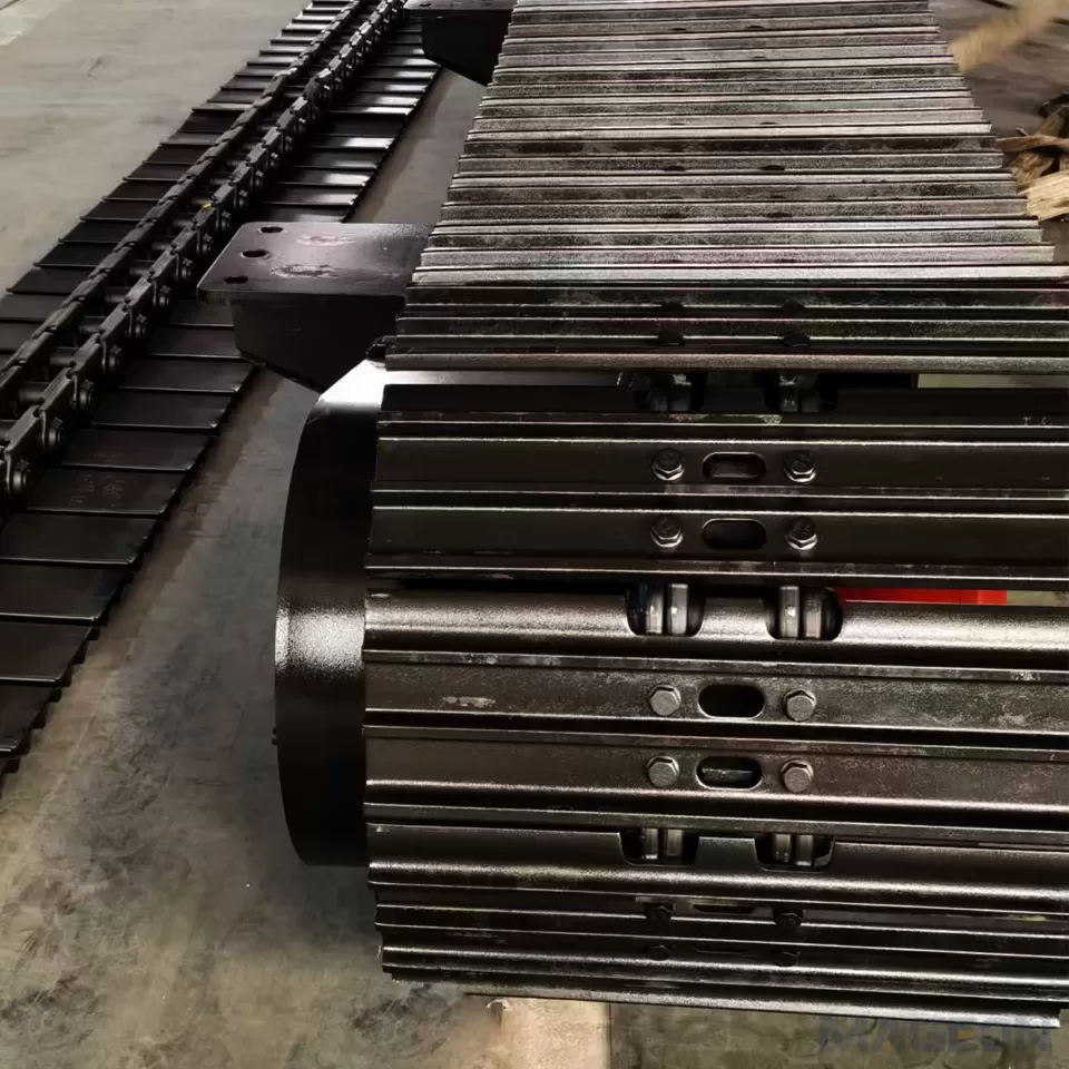
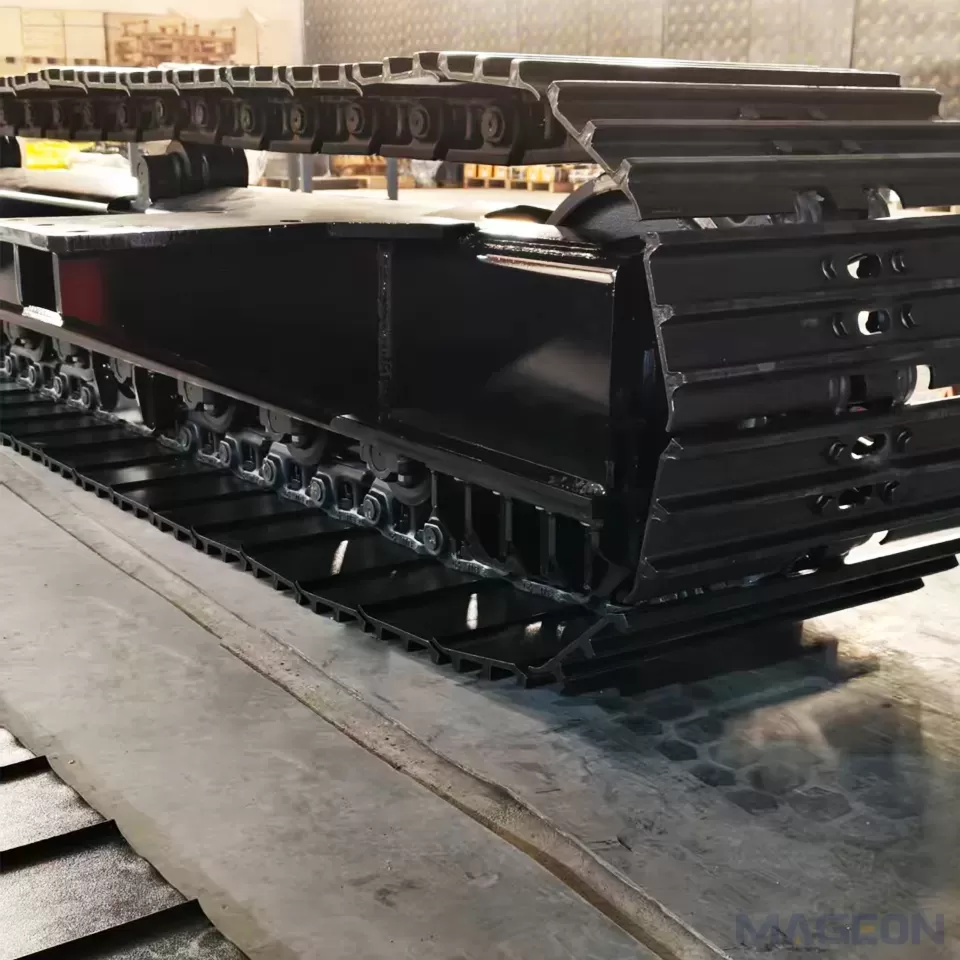
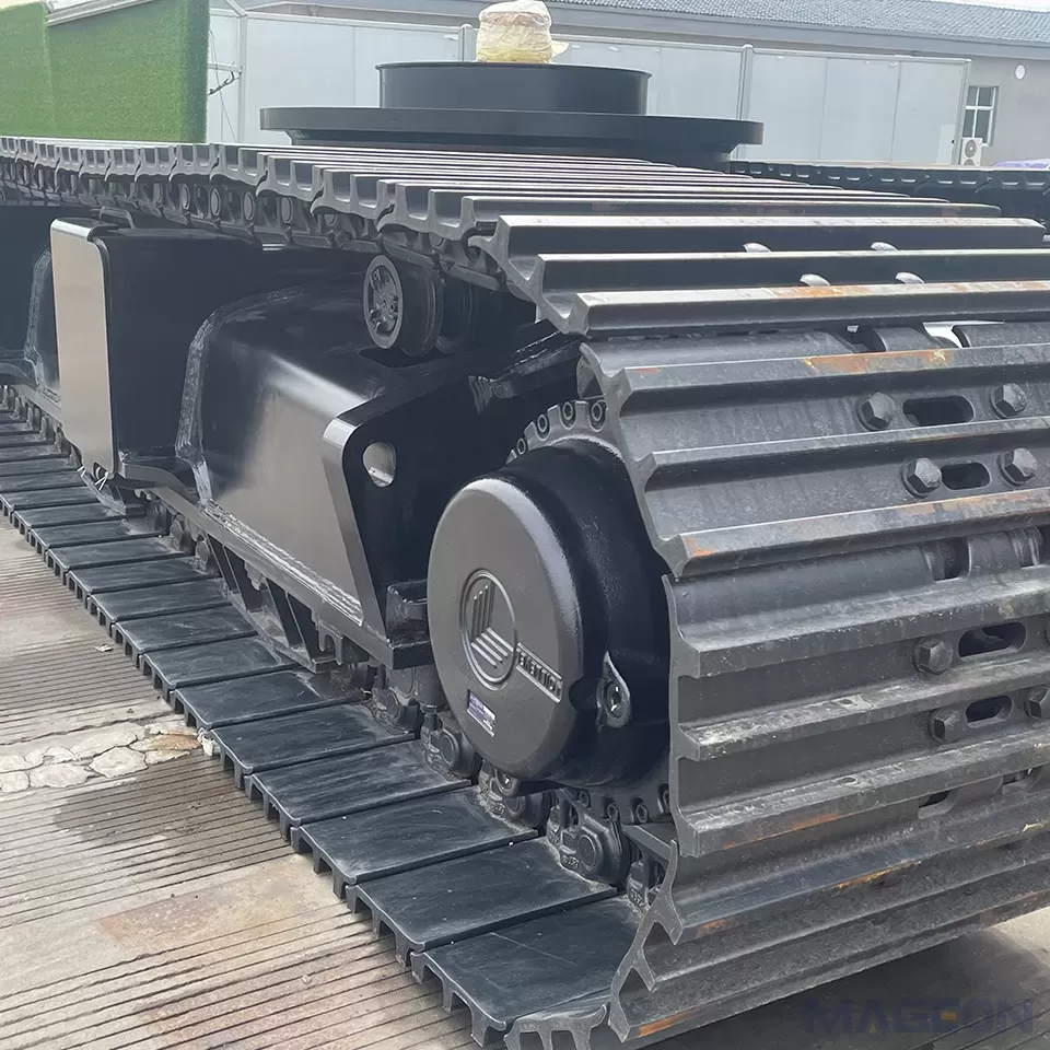
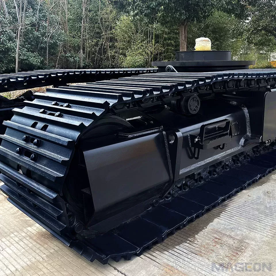
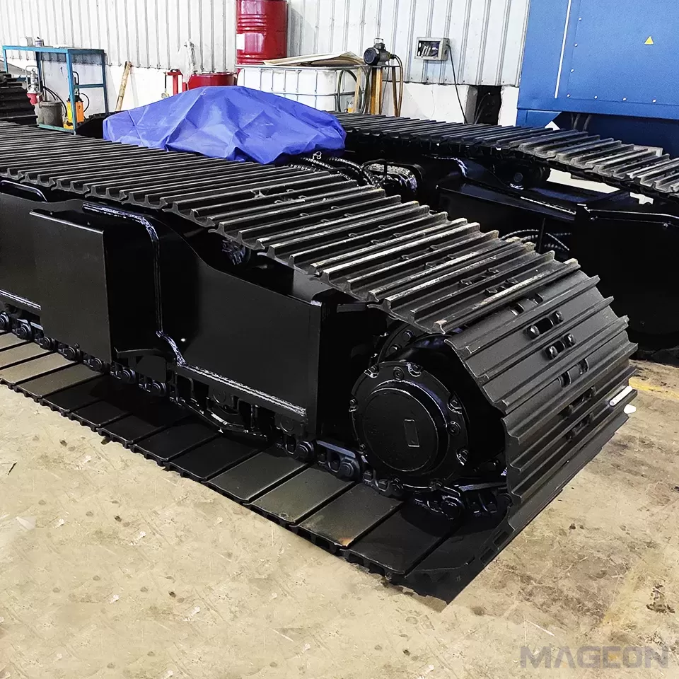
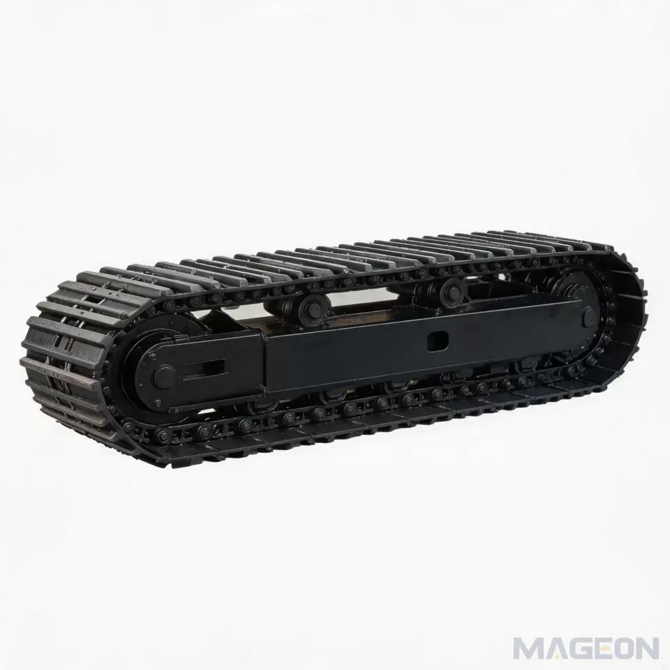
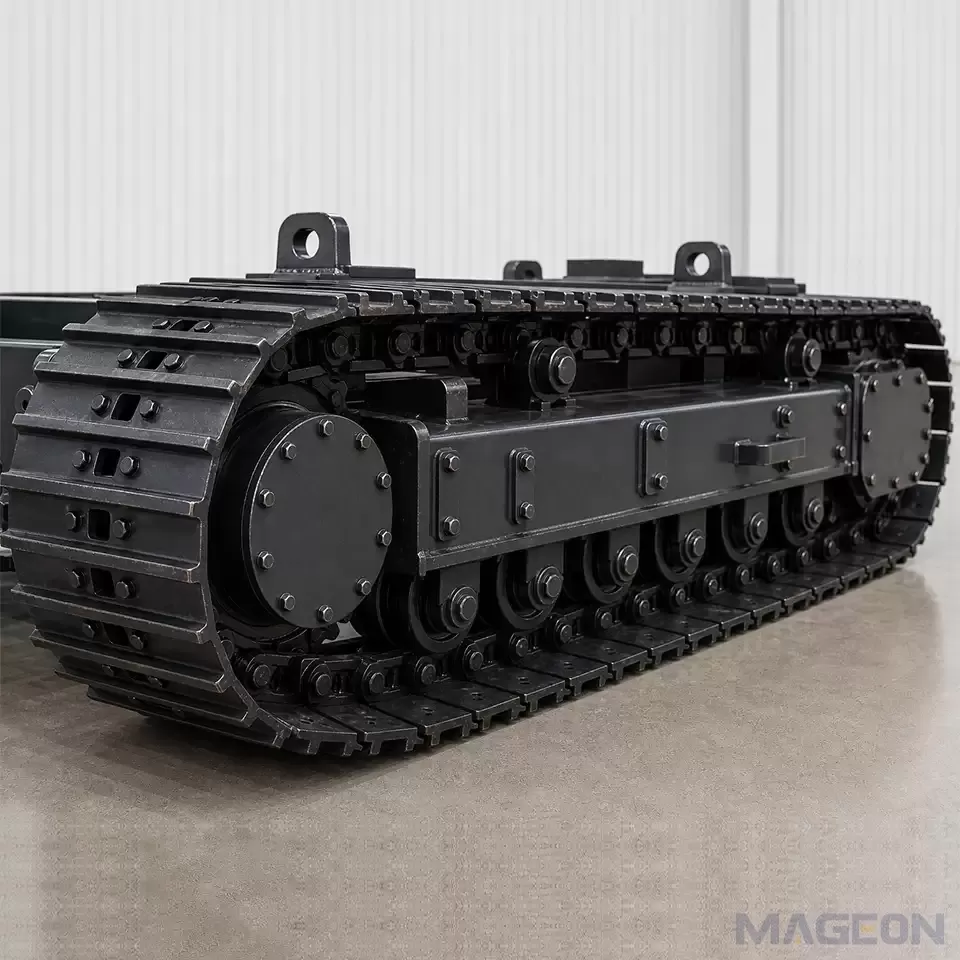
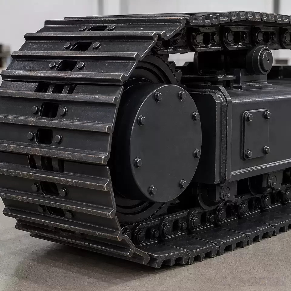
The drive sprocket is connected to the final drive. As it rotates, successive teeth engage the chain interface—commonly the bushings or the corresponding link geometry—and pull the chain around the undercarriage. Caterpillar describes the sprocket segment as a component that interfaces with track links to drive the equipment in its official track segment documentation. The exact contact arrangement varies with the chain and sprocket design, so the approved component drawings remain authoritative for a specific project.
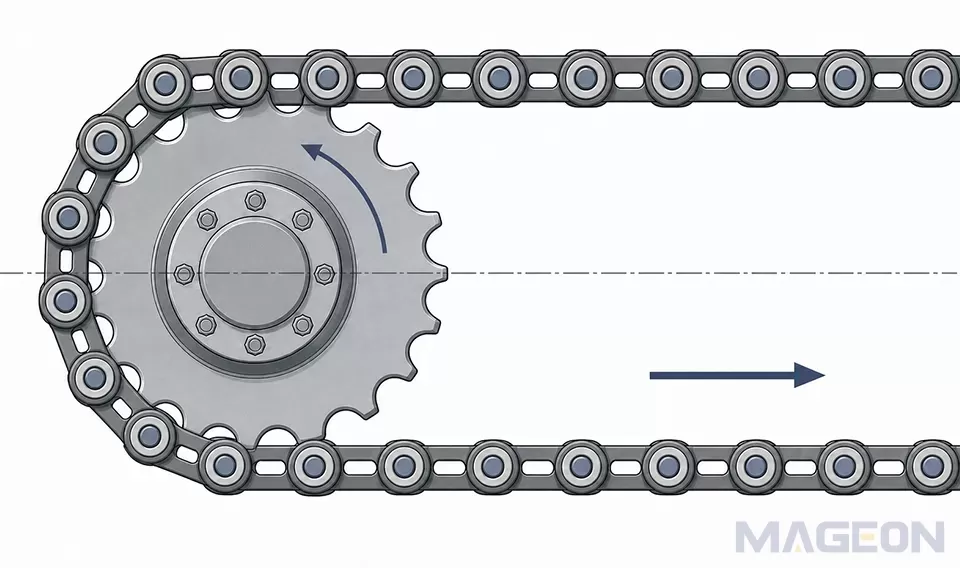
Figure 1: Conceptual sprocket-to-track-chain engagement and consistent motion directions; not a product drawing or dimensional specification.
Force is not transferred through a generic circular wheel. It passes through changing contact points as teeth enter, carry load, and leave engagement. The exact share carried at each point depends on the matched geometry, track tension, alignment, deformation under load, and component condition. This is why visual fit at rest is not sufficient evidence of correct engagement under drive torque.
The same interface must also tolerate direction changes, steering events, contamination, and impact transmitted through the track system. These conditions do not establish a universal sprocket design; they define the inputs that an engineer must consider when specifying the pair.
Which Geometry Must Match Between the Sprocket and Track Chain?
Pitch is the first compatibility check, but not the only one. Komatsu defines link pitch as the center distance between link pins and sprocket pitch as the distance between teeth along the sprocket pitch line. Its official sprocket technical page states that these pitches are equal on a new matched system.
Tooth profile, bushing or link contact geometry, tooth width, lateral clearance, chain guidance, mounting position, and the interface with the final drive also matter. A matching pitch value alone does not prove that the full assembly is compatible. The correct combination should be verified from controlled drawings or supplier data for both components.
| Why it matters | What the OEM should verify | |
|---|---|---|
| Chain and sprocket pitch | Establishes the repeating engagement spacing | Exact definitions, units, and drawing revisions match |
| Tooth and chain contact geometry | Controls where contact begins, carries load, and releases | Sprocket profile is intended for the specified chain interface |
| Tooth width and lateral position | Influences side contact and chain guidance | Chain centerline, sprocket centerline, and available clearance are compatible |
| Mounting and drive interface | Positions the sprocket relative to the frame and final drive | Mounting pattern, offset, rotation direction, and adjacent clearances are confirmed |
| Track adjustment range | Changes how the chain approaches and leaves the sprocket |
These checks identify what must be controlled; they do not supply final values. Project drawings should define the dimensions and tolerances used for manufacturing and inspection.
How Does Wear Change the Engagement Pattern?
Engagement changes as the chain and sprocket wear. Komatsu explains that pin and bushing wear can extend link pitch while tooth-surface wear can change effective sprocket pitch. As the two become less well matched, contact can shift and abnormal wear can develop at the bushing outside diameter and sprocket tooth surface. This is a mechanism to inspect, not a universal wear-rate prediction.
Wear state matters when deciding whether to reuse, replace, or combine parts. Installing one new component next to a substantially worn mating component may create a different contact pattern from a new matched set. That does not mean every mixed replacement is prohibited; it means the actual condition, manufacturer guidance, measured wear, and maintenance objective must be evaluated together.
Track condition also affects how the chain enters the sprocket. Correct track tension and sag must follow the equipment manufacturer's procedure because excessive tightness or looseness can alter loads and accelerate undercarriage wear. Komatsu's undercarriage maintenance guidance specifically directs operators to use the adjustment specification in the machine's operation and maintenance manual.
What Can Poor Engagement Look Like?
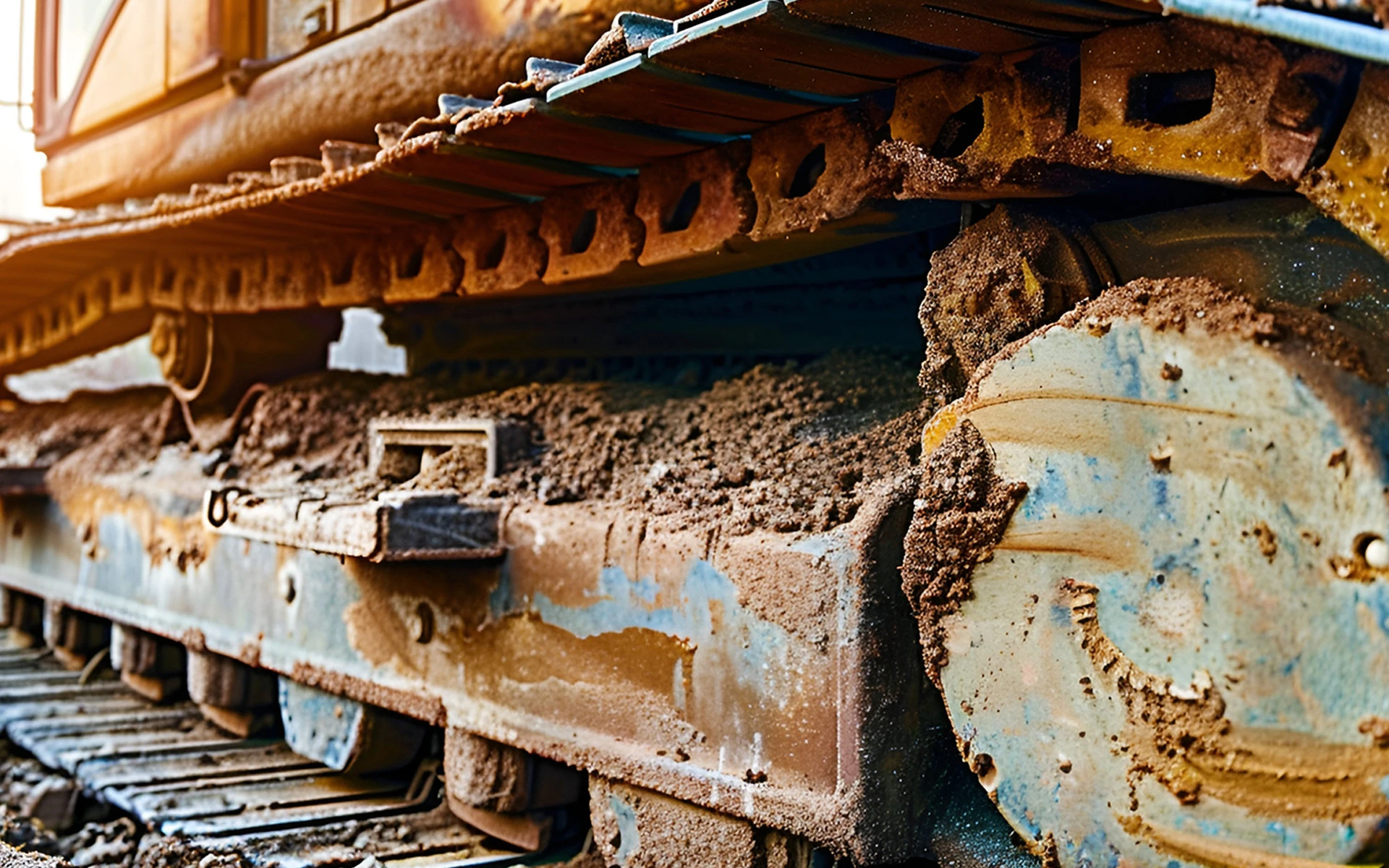
Poor engagement does not have one exclusive symptom. Repeated impact, irregular running, asymmetric contact marks, localized polishing, accelerated tooth or bushing wear, and a chain that appears to enter the sprocket unevenly can all justify inspection. Each observation can also have other causes, including track adjustment, contamination, damaged components, frame distortion, guidance problems, or measurement error.
| Possible engagement relationship | Required check | |
|---|---|---|
| Contact concentrated on one side | Sprocket and chain centerlines may not be aligned | Verify mounting faces, offsets, frame condition, and lateral guidance |
| Repeated impact during engagement | Pitch, profile, tension, or wear state may be incompatible | Compare component identity and measurements with approved service limits |
| Localized tooth or bushing wear | Load may not be distributed as intended | Inspect the complete contact pattern and mating-component condition |
| Uneven chain entry or exit | Adjustment, debris, guidance, or geometry may be affecting the path |
These are screening clues, not remote diagnoses. A broader review of crawler undercarriage wear patterns is needed before attributing damage to the sprocket-chain interface alone. Stop operation and follow the equipment manufacturer's safety and service procedures whenever the condition could affect safe travel or component retention.
What Should OEMs Verify Before Selecting a Sprocket and Track Chain?
Start with controlled component identity. The chain designation, pitch, link or bushing interface, sprocket drawing, and revision status should agree across engineering, purchasing, production, and service records. A commercial description or an approximate measurement is not enough for release.
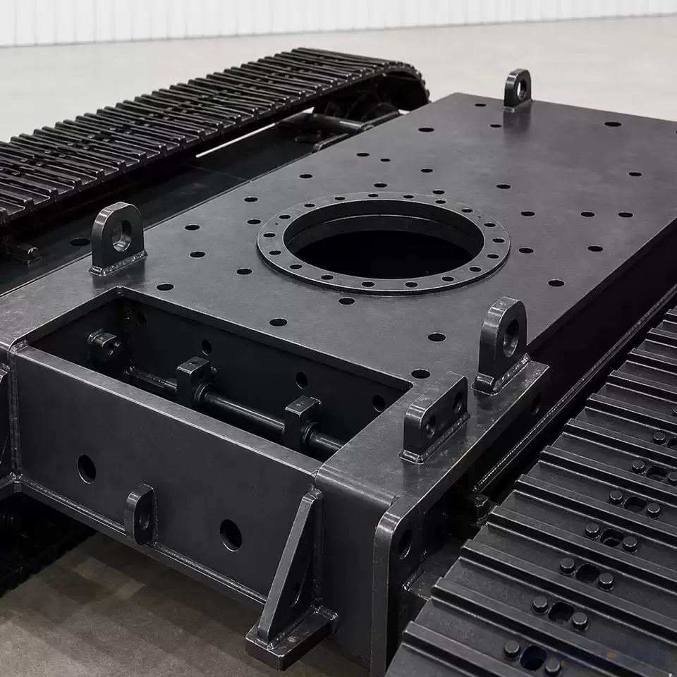
Next, verify the installed geometry. Confirm sprocket offset, chain centerline, final-drive mounting, frame interfaces, clearance through the full adjustment range, and guidance near the drive end. Evaluate tolerances as an assembled stack rather than checking each part in isolation.
Then connect the geometry to duty. Required drive torque, travel speed, direction changes, steering behavior, shock exposure, contamination, duty cycle, and maintenance practice can influence loading and wear. These inputs help the engineer judge whether the proposed component pair and maintenance strategy are appropriate; they do not automatically produce a final design.
Finally, define replacement and inspection logic before the machine enters service. Specify which measurements identify wear, where they are taken, which source defines the service limit, and whether mating components must be evaluated together. Purchasing should also confirm traceability to the approved drawings so that a substitute does not change a critical interface without review.
What Information Should Be Supplied for Engineering Evaluation?
An OEM requesting an evaluation of complete crawler undercarriage assemblies should provide enough information to connect the drive interface to the whole machine:
equipment type, operating mass, payload, and relevant load cases;
required travel speed, drive torque or available hydraulic drive data, and expected steering behavior;
track chain identification, pitch, interface dimensions, drawing revision, and current wear condition when applicable;
sprocket identification, tooth count, profile or controlled drawing, mounting offset, and final-drive interface;
track gauge, ground contact length, sprocket and idler centers, adjustment range, and frame mounting information;
alignment requirements and the planned inspection method;
terrain, contamination, gradient, duty cycle, travel direction pattern, and maintenance environment;
applicable standards, customer specifications, and service expectations.
Missing information should be identified explicitly. It is safer to pause a configuration decision than to infer pitch, tooth geometry, torque capacity, material, heat treatment, or wear limits from a similar-looking part.
Frequently Asked Questions
Is matching the chain pitch enough to confirm compatibility?
No. Pitch is essential, but tooth profile, contact geometry, width, lateral position, mounting interface, clearance, and approved drawing revision also need to agree. Final compatibility requires project-specific verification.
Can a new sprocket be used with a worn track chain?
It may be possible in some service strategies, but it should not be assumed. Measure both components, consult the applicable maintenance limits, and evaluate how their wear states affect the contact pattern before making the replacement decision.
Does incorrect track tension cause poor sprocket engagement?
Track tension can influence how the chain approaches and leaves the sprocket and how loads move through the undercarriage. It is one factor among several, so adjustment should follow the equipment manual and should not replace checks of pitch, alignment, wear, and component identity.
Why does lateral alignment matter?
The sprocket and chain need compatible centerlines and clearance. Misalignment can move contact toward one side and add lateral loading, but the observed marks should be assessed together with guidance, frame condition, and installation measurements.
Can noise confirm that the sprocket and chain are mismatched?
No. Repeated impact or unusual noise is a reason to inspect the system, not proof of one cause. Debris, adjustment, damaged parts, guidance, final-drive condition, and other sources should also be checked.
Which document should define the final sprocket dimensions?
Use the latest approved drawing, technical data sheet, or engineering confirmation for the specific chain and machine. Catalog examples and general articles can explain selection logic but should not replace controlled project data.
Sprocket-to-track-chain engagement should be treated as a system decision across geometry, installation, duty, wear, and service planning. For a technical evaluation or project inquiry, provide the equipment, load, drive, dimensional, interface, and duty-condition information needed to assess the complete undercarriage configuration.
Please leave your customization requirements, and we will contact you as soon as possible!
Leave your requirements, we'll get back to you within 24 hours.