What Should Piling Rig OEMs Confirm Before Selecting a Crawler Undercarriage?
Before selecting a piling rig crawler undercarriage, an OEM should confirm the machine configurations, load cases, center-of-gravity data, ground conditions, travel requirements, mounting interfaces, hydraulic supply, and transport constraints. The equipment name or nominal operating weight alone is not enough.
What Must Be Confirmed Before Undercarriage Selection?
The first task is to build a shared input set. The OEM owns the whole-machine definition and application requirements. The undercarriage supplier can then evaluate a proposed track system against those inputs, while stability, structural integration, transport compliance, and final machine approval remain project-specific responsibilities.
| What the OEM should provide | Why it affects selection | Who confirms it | |
|---|---|---|---|
| Machine configuration | Piling method, mast or leader, tool, counterweight, auxiliary equipment | Defines the physical and load envelope | OEM equipment team |
| Load cases | Mass, center of gravity, working reactions, attachment positions | Establishes the cases the structure and contact system must be evaluated against | OEM structural and stability engineers |
| Site conditions | Ground support, slope, obstacles, contamination, duty cycle | Affects contact, mobility, wear exposure, and recovery planning | OEM and project owner |
| Travel duty | Speed, distance, turning frequency, grade, drawbar demand | Influences drive, braking, thermal, and traction requirements | OEM system engineers |
| Integration | Mounting structure, clearances, hoses, controls, service access | Determines whether the undercarriage can be installed and maintained | OEM and undercarriage supplier |
| Transport | Shipping envelope, disassembly plan, tie-down method, loading procedure | May require a state different from the working configuration |
These inputs are connected. For example, reducing transport width may require retractable side frames, but that decision also affects structure, hydraulic routing, locking, setup procedures, and the geometry available in the working state. Treat each change as a whole-machine design input, not as an isolated catalog choice.
Define the Piling Method and Machine Configurations
“Piling rig” can describe machines using rotary drilling tools, vibrators, hammers, augers, mixing tools, or combined systems. Each attachment arrangement changes mass distribution, working geometry, hydraulic demand, and the way the machine is prepared for transport. The OEM should therefore identify the intended methods and the permitted attachment combinations before asking for an undercarriage proposal.
The input package should define at least three states: working, site mobilization, and transport. A working state may use an erected leader and an extended undercarriage. Mobilization may involve short-distance travel with a restricted attachment position. Transport may require a folded leader, removed tooling, reduced counterweight, or retracted track frames. These are examples of state definitions, not universal configurations.
Official product documentation shows why this separation matters. Liebherr describes its LRB 23 as transportable as a single unit, while other designs may use different preparation steps; the relevant point for an OEM is to document the intended state rather than assume one transport method applies to every rig. Liebherr LRB 23 product information
| Attachments and position | Load data required | Undercarriage checks | |
|---|---|---|---|
| Working | Defined leader, tool, counterweight, and working radius | Total mass, component masses, centers of gravity, reactions | Working geometry, contact conditions, structure, stability inputs |
| Site mobilization | Approved travel position and installed equipment | Travel-state mass and center of gravity | Traction, braking, clearance, slope, travel limits |
| Transport | Folded or removed assemblies and shipping restraints | Transport mass, dimensions, support and tie-down loads |
Establish Loads, Center of Gravity, and Working Reactions
Start with a load-case dossier, not a single weight value. It should identify the mass and center of gravity of the base machine, leader or mast, counterweight, tool, hoses, auxiliary systems, and any removable assemblies. It should also cover the permitted positions of those items in every relevant machine state.
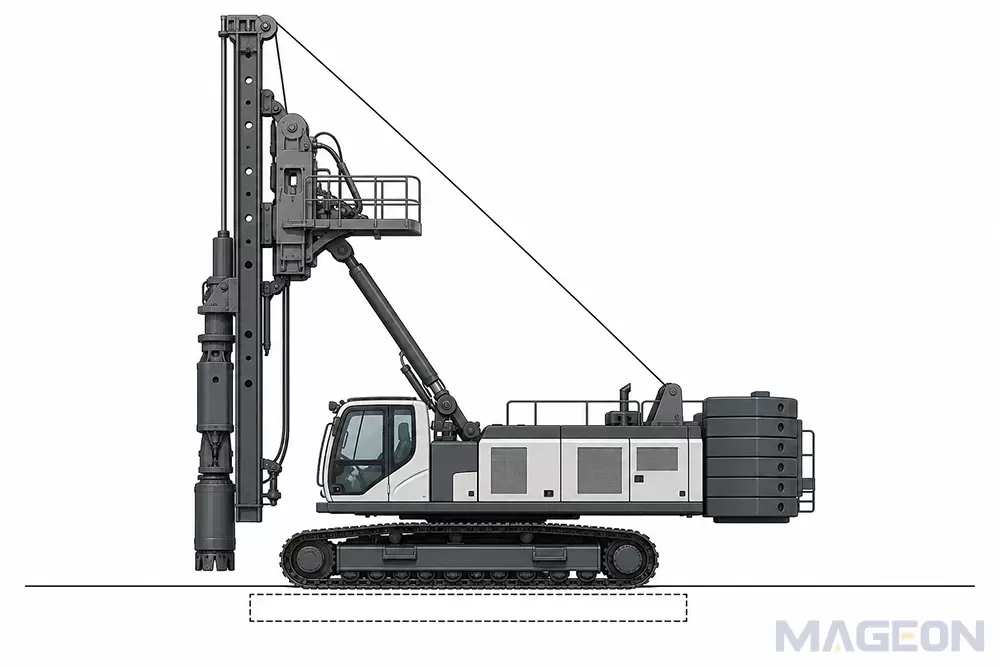
For a deeper explanation of how location changes the machine-level assessment, see the approved topic on crawler undercarriage center of gravity. In this application, the important step is to provide coordinates and load cases that the engineering teams can use, rather than describing the center of gravity only as “low” or “central.”
Working reactions also need separate treatment. Crowd, extraction, driving, vibration, tool engagement, and auxiliary operations can create cases that are not represented by static machine mass. The OEM should define the direction, duration, combination, and design basis of these reactions. The undercarriage supplier should not infer them from the machine category.
Stability and ground pressure are whole-machine results. They depend on the confirmed configuration, support geometry, contact assumptions, ground conditions, operating procedure, and applicable engineering method. An undercarriage proposal can supply component data and geometry for that assessment, but it does not replace it.
Match Undercarriage Geometry to Stability, Ground Contact, and Packaging
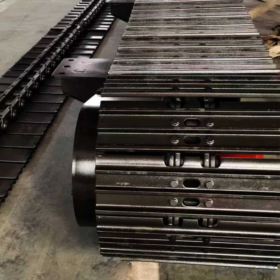
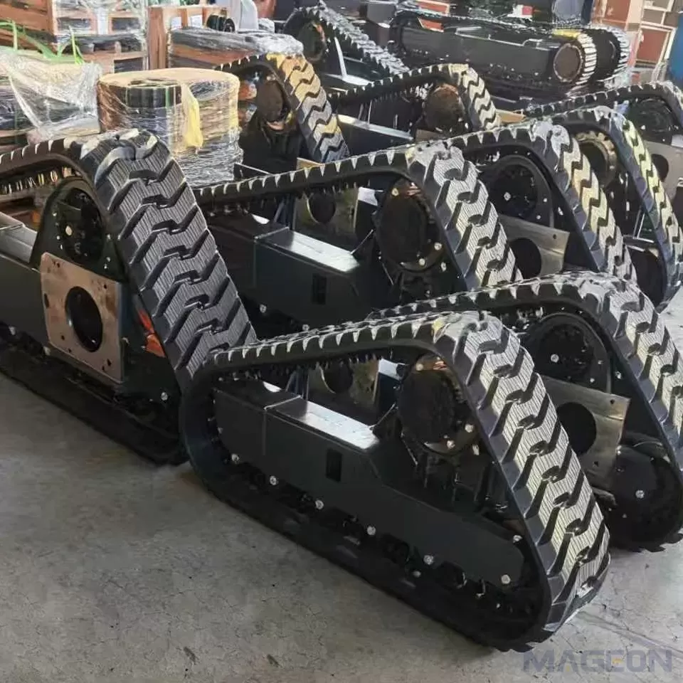
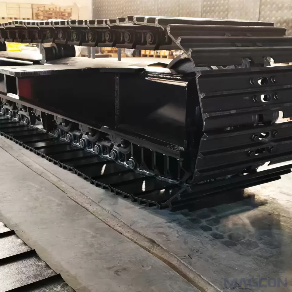
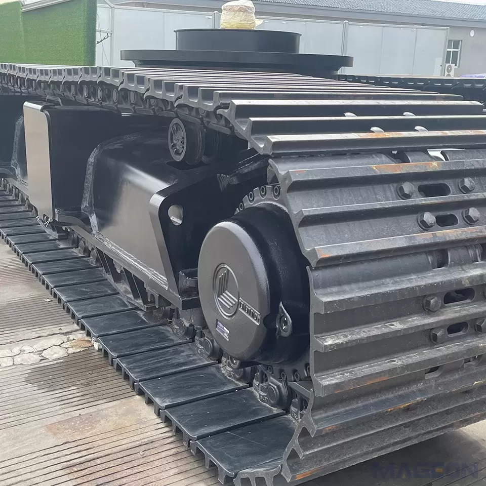
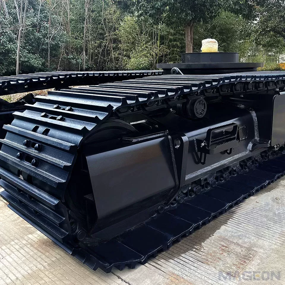
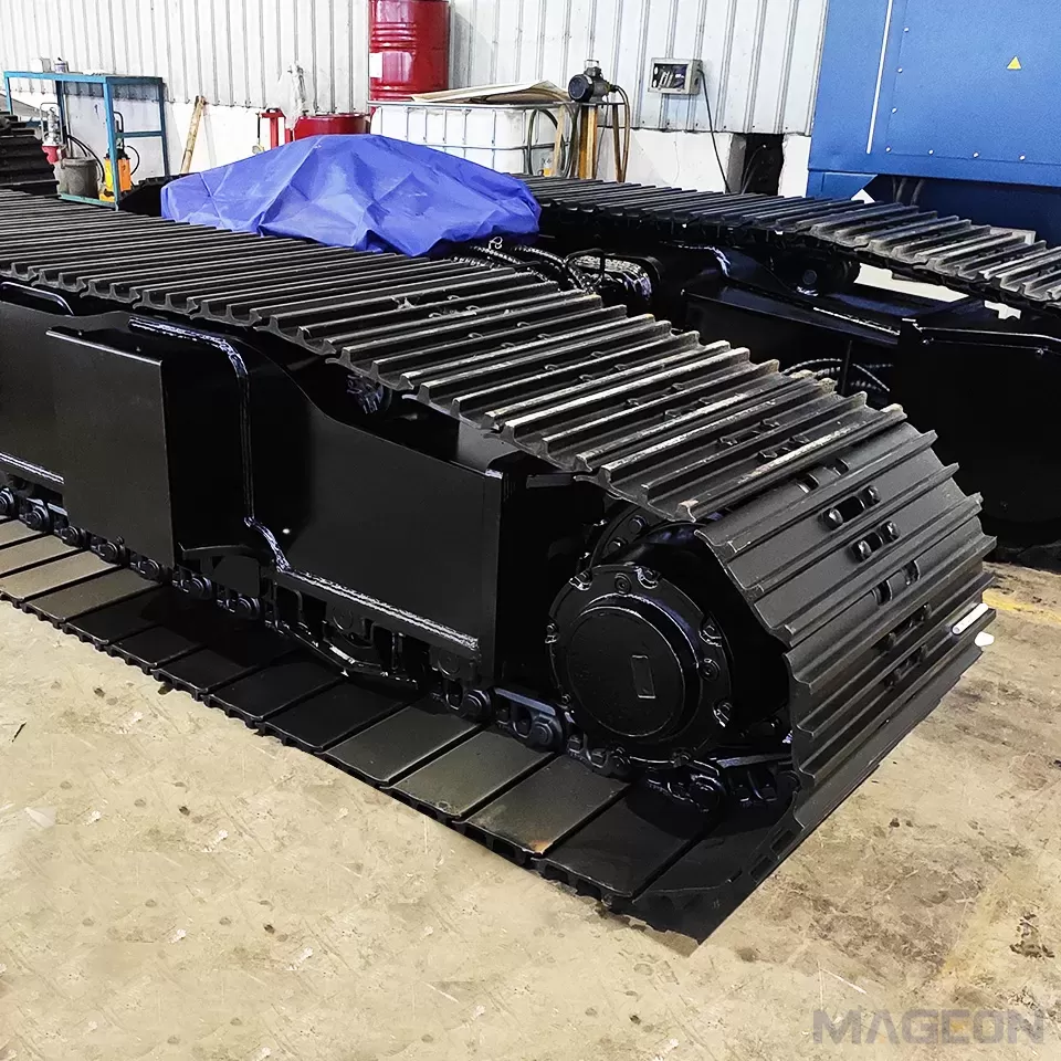
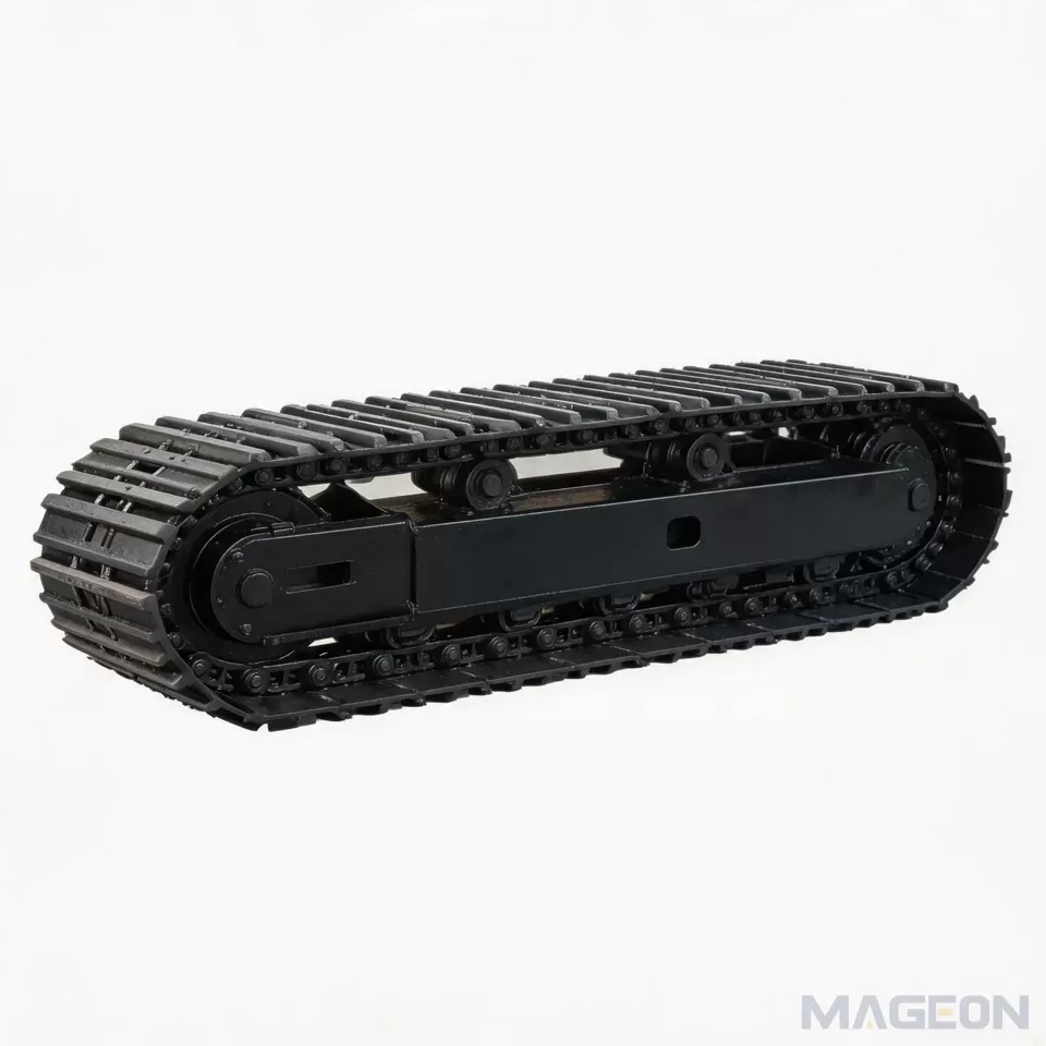
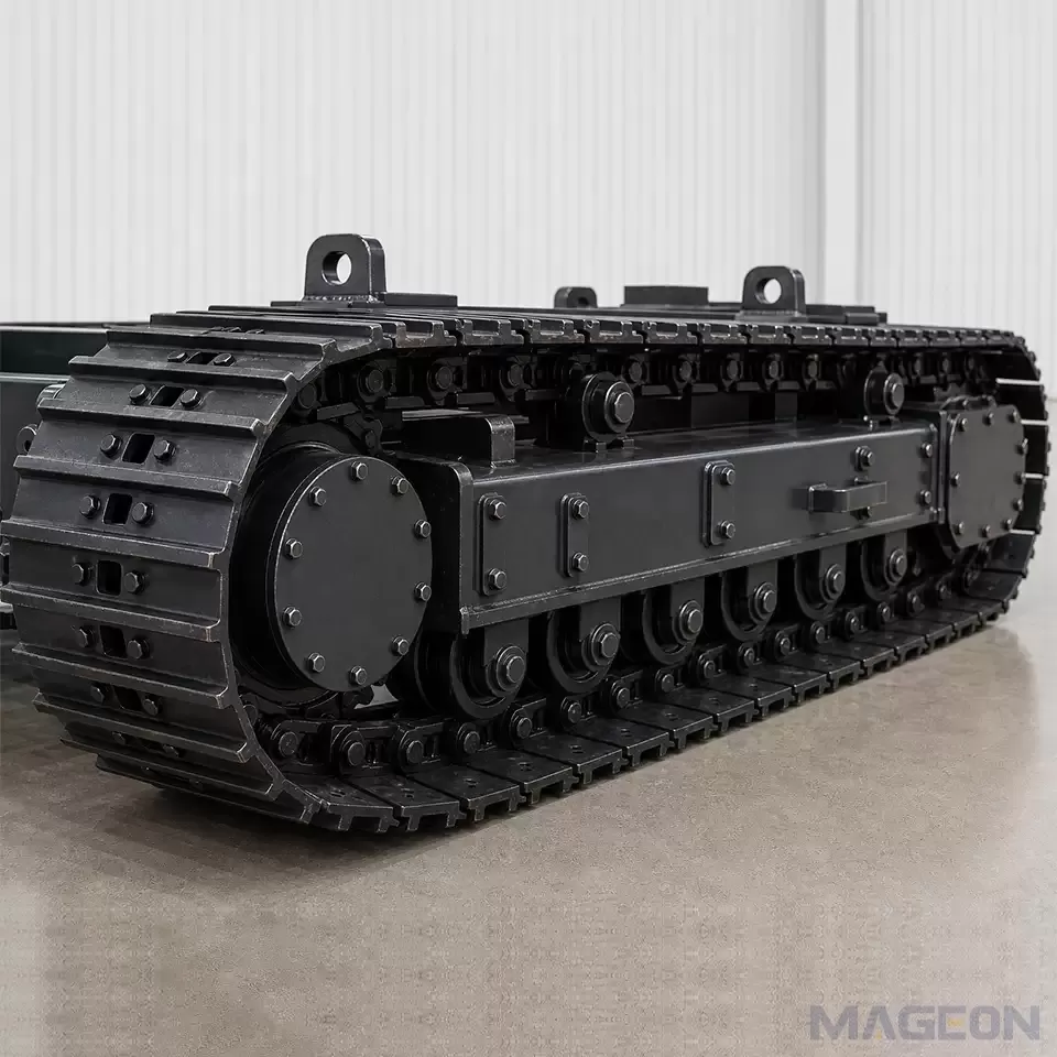
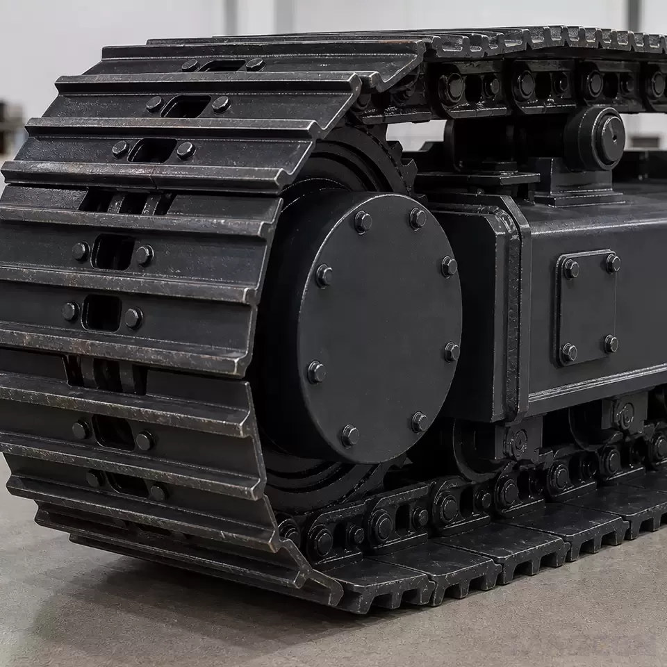
Track shoe width, track gauge, ground contact length, overall track length, frame height, and retracted or extended width all affect more than one decision. Wider support geometry may assist a particular working layout but can conflict with transport limits or surrounding equipment. A longer contact region can change packaging and turning behavior. Track shoe selection also interacts with ground conditions, steering resistance, component loading, and transport width.
The approved article on crawler undercarriage track gauge provides the parameter-level background. For a piling rig project, the OEM should connect that principle to the actual upperstructure, leader positions, counterweight, slew envelope, access requirements, and transport plan.
Manufacturer technical sheets illustrate the field structure that an OEM may need to define. Casagrande, for example, publishes retracted and extended undercarriage width, track shoe width, overall track length, travel speed, and traction force for specific piling rig models. Those model values are not transferable to another machine, but the data categories are useful when preparing an input specification. Casagrande CB26 technical data
Final geometry still requires coordinated checks for structure, interference, service access, hose movement, frame locking, ground contact, and transport.
Check Travel, Traction, Terrain, and Hydraulic Requirements
Define how the machine will travel, not merely whether it can travel. Required inputs include maximum and normal travel speed, distance per cycle, turning frequency, expected grades, obstacle transitions, ground surface, ambient conditions, contamination, and whether travel occurs with attachments installed. Recovery and towing provisions may also be relevant to the machine risk assessment.
Drawbar demand and gradeability cannot be specified safely from machine mass alone. Ground interaction, slope, rolling resistance, steering behavior, drive efficiency, attachment position, and allowable operating procedure all matter. The OEM should supply the project assumptions and required safety margins; the drive and hydraulic system should then be checked against those cases.
Hydraulic inputs should include available pressure and flow, circuit arrangement, control logic, braking philosophy, cooling assumptions, allowable back pressure, hose routing, and interfaces with the machine control system. Final motor, gearbox, brake, valve, and reduction selections require matched calculations and approved component data.
Define Mounting Interfaces and Whole-Machine Integration
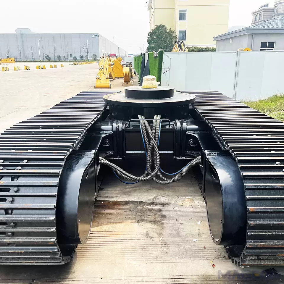
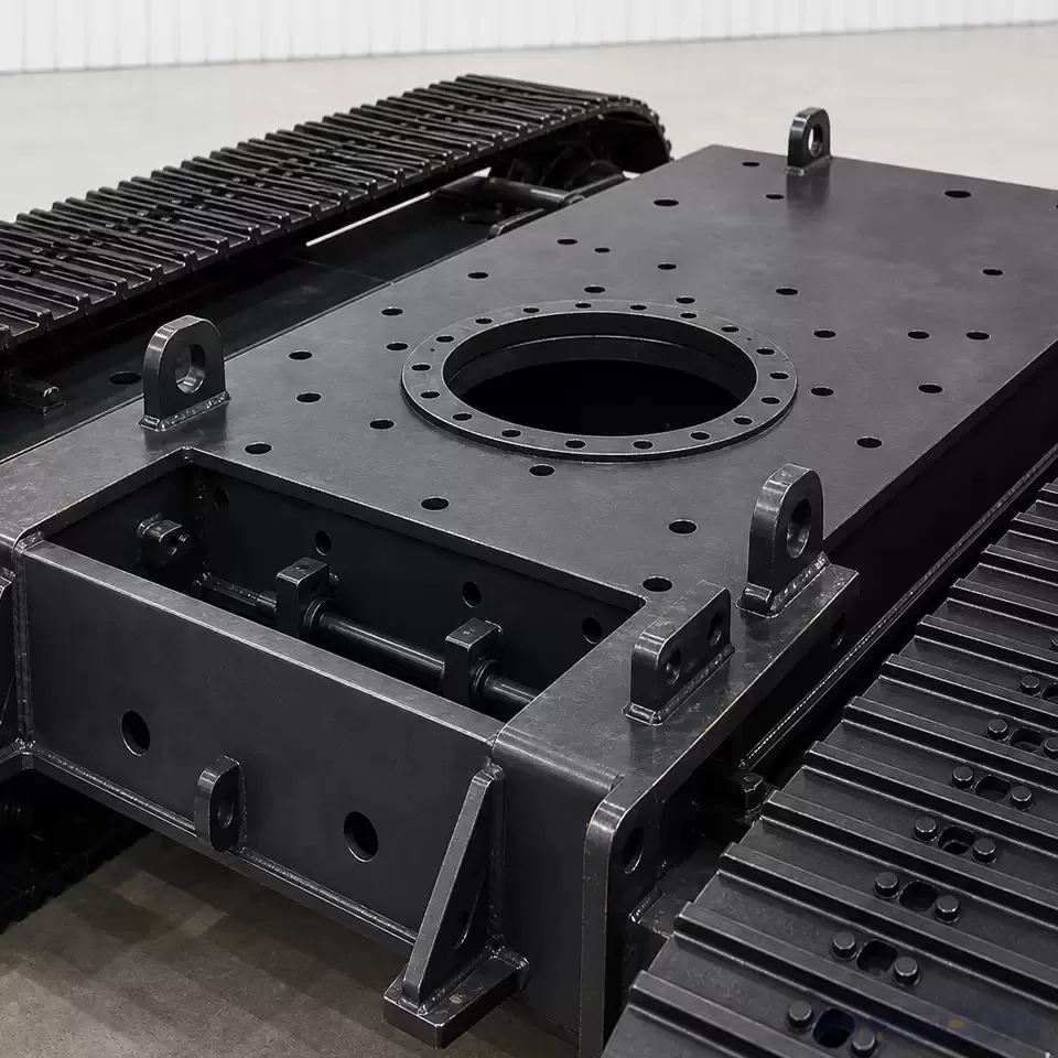
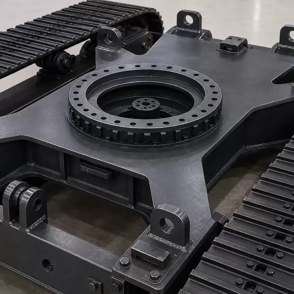
Interface control should begin with an approved drawing set. The relevant crawler undercarriage mounting dimensions may include mounting faces, bolt or weld zones, locating features, slew-bearing or upper-frame interfaces, centerlines, allowable envelopes, and datum definitions. The OEM should also identify loads and moments at the interface and the structural method used to verify them.
Integration extends beyond the mounting pattern. Check hydraulic and electrical routing through the complete movement range, clearance to rotating or folding structures, protection from debris, access for inspection and tension adjustment, lubrication points, lifting or handling provisions, and assembly sequence. If retractable frames are proposed, define actuation, locking, position confirmation, hose accommodation, and the conditions under which movement is permitted.
A similar envelope or bolt pattern does not prove structural, hydraulic, control, or safety compatibility.
Separate Operating Setup From Transport and Site Mobilization
Transport is a separate configuration-management problem. Record what remains installed, what is folded or removed, how the machine is loaded, where it is supported and secured, and how the working configuration is restored and verified at the site. Legal road limits and carrier requirements vary by destination, so the OEM must confirm the applicable rules for the actual route and transport method.
Safety features and procedures must also match the design. In an official description of changes associated with EN 16228, Soilmec discusses remote control for loading and unloading and transport anchor points located on the undercarriage. This is a manufacturer-specific example, not proof that another design complies with the standard, but it demonstrates why loading controls and securing interfaces should be defined early. Soilmec EN 16228 safety improvements
Prepare the OEM Input Package for Technical Evaluation
A concise dossier reduces repeated clarification and prevents a preliminary concept from being mistaken for an approved design.
| Required detail | Source or owner | Confirmation output | |
|---|---|---|---|
| Equipment definition | Piling methods, configurations, drawings, attachment list | OEM product engineering | Agreed design scope |
| Load dossier | Masses, centers of gravity, reactions, combinations, design basis | OEM structural team | Approved load cases |
| Geometry | Envelopes, interfaces, clearances, working and transport states | OEM layout team | Interface-controlled layout |
| Site and travel duty | Ground, slopes, distances, speeds, turns, environment, duty cycle | OEM and project owner | Defined mobility cases |
| Hydraulic and controls | Pressure, flow, cooling, braking, logic, connectors | OEM hydraulic and controls teams | Interface and performance requirements |
| Compliance and logistics | Destination rules, risk assessment, loading and securing method | OEM safety and logistics teams |
The supplier response should state its assumptions, proposed configuration, required interfaces, excluded conditions, data still needed, and the verification work that remains with each party. Any later change to attachment, counterweight, working radius, transport state, or duty condition should trigger an impact review.
Frequently Asked Questions
Can operating weight alone determine the crawler undercarriage?
No. Operating weight does not describe center-of-gravity location, attachment position, working reactions, support geometry, travel duty, or transport state. These inputs must be evaluated together.
Should the tracks always be as wide as transport limits allow?
No. Track shoe width and overall support geometry involve ground contact, steering, structural, wear, packaging, and transport tradeoffs. The correct choice depends on confirmed machine and site requirements.
Does a retractable undercarriage solve both stability and transport requirements?
It can provide different working and transport widths, but it also introduces structural, hydraulic, locking, sensing, hose-routing, and procedural requirements. Both states still require independent verification.
Who is responsible for piling rig stability verification?
Responsibility must be defined by the project and applicable rules, but stability is a whole-machine engineering assessment. Undercarriage data supports that work; it does not by itself approve the complete machine.
What hydraulic information should an OEM provide?
Provide available pressure and flow, circuit architecture, cooling assumptions, allowable back pressure, braking and control logic, connection details, and expected travel duty. Component selection should be based on the matched system and verified load cases.
When should an undercarriage proposal be reviewed again?
Review it when masses, centers of gravity, attachments, reactions, geometry, travel duty, site conditions, transport configuration, or interfaces change. The review should determine whether earlier calculations, drawings, or approvals remain valid.
For a project-specific technical evaluation, provide the equipment type, piling method, attachment combinations, mass and center-of-gravity data for each configuration, machine dimensions, ground and slope conditions, travel duty, mounting interfaces, and hydraulic information.
Please leave your customization requirements, and we will contact you as soon as possible!
Leave your requirements, we'll get back to you within 24 hours.