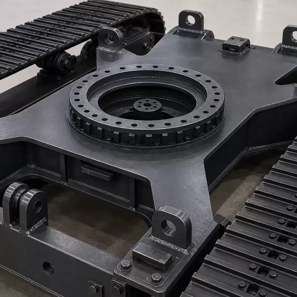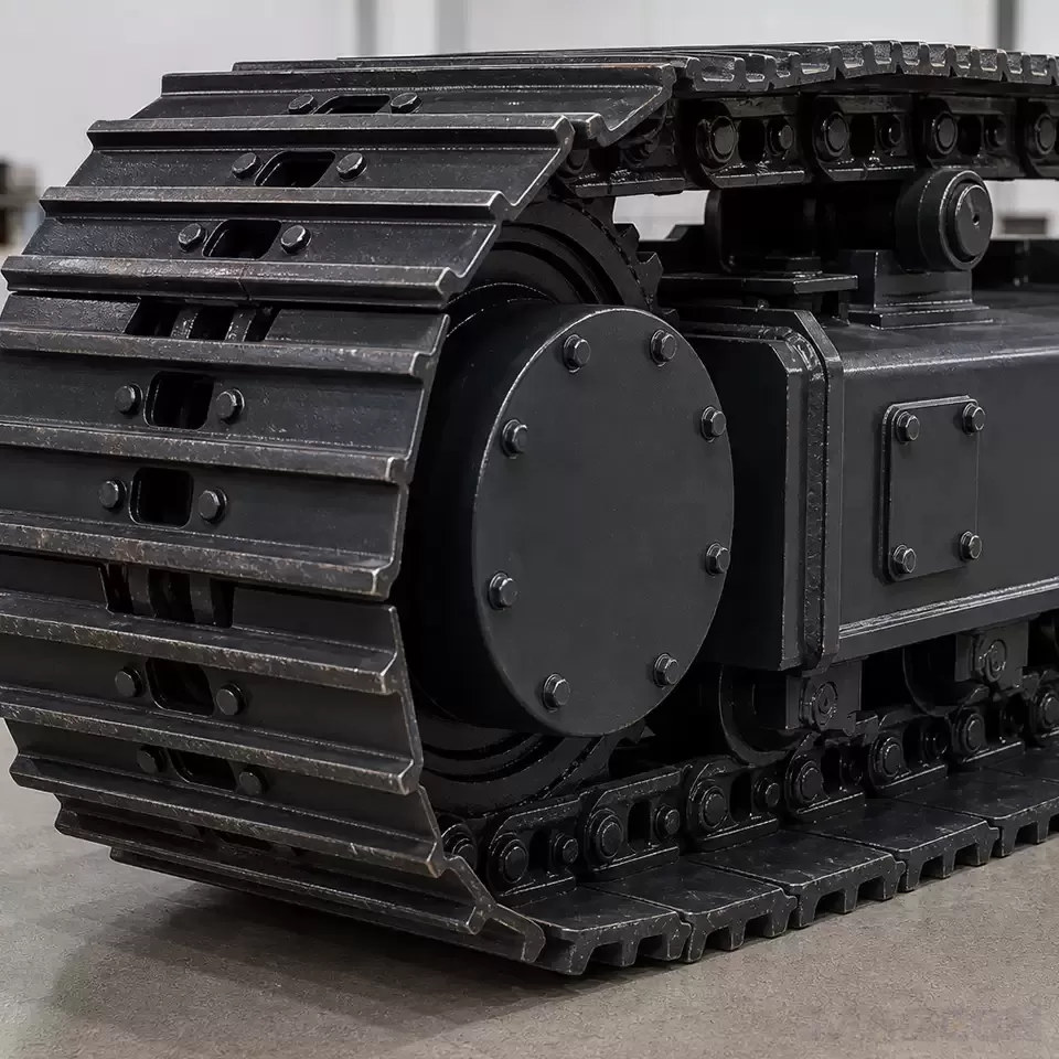

How Do Idlers and Tensioning Devices Work Together in a Crawler Undercarriage?
An idler and a tensioning device should be considered together because each belongs to the same crawler track loop, yet they answer different questions. At a general level, the idler provides a defined wheel location for the loop at one end of the undercarriage, while the tensioning device is associated with establishing the intended loop condition through the idler arrangement. Neither component can be selected or discussed responsibly as an isolated catalogue item when the machine layout, track chain, interfaces, and controlled project documents are still unknown.
For an OEM team, the useful first step is not to infer a final structure from a generic diagram. It is to separate the questions that concern guidance, tensioning, track-loop condition, mounting, and service access, then identify which project records are authoritative for each question. This article provides that preparation framework; it does not prescribe a setting, travel, internal mechanism, maintenance procedure, or final configuration.
Why Idlers and Tensioning Devices Must Be Considered Together
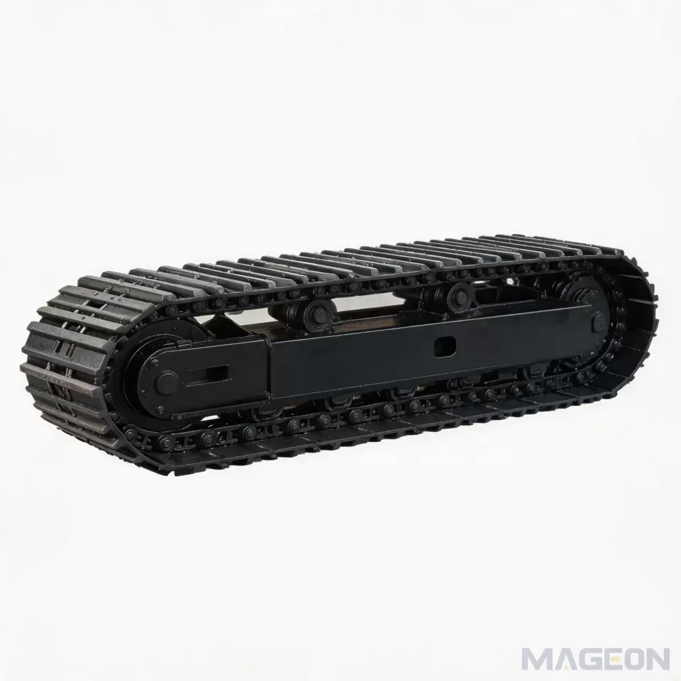
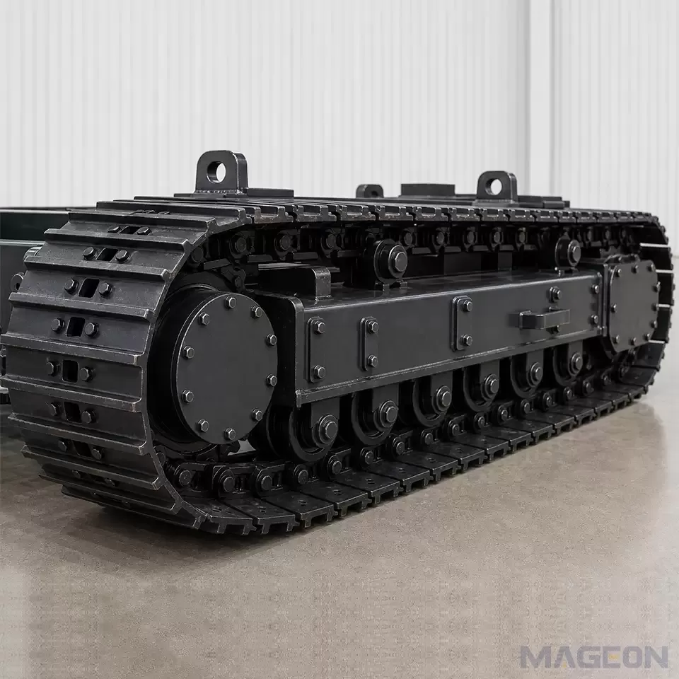
The crawler idler and tensioning device share a system context: the continuous track loop. A conceptual drawing can show their relative relationship, but it cannot confirm how a particular machine is built or how it should be adjusted.
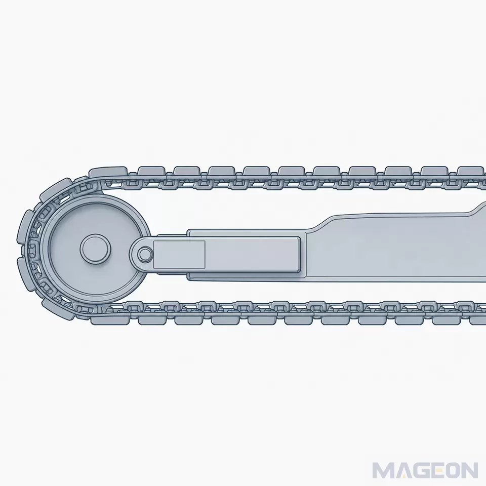
In a project discussion, an idler is not simply “the wheel at the front.” Its relevance depends on the whole loop and on the approved arrangement around it. Similarly, calling a component a tensioning device does not establish its specific construction, available movement, adjustment method, or suitability for a given machine. Those details require the latest approved drawing, technical data sheet, or engineering confirmation.
Treating the two items together prevents a common communication problem: one party may be asking about the physical location of an idler, while another is asking about the intended condition of the track loop. The names sound related, but the evidence needed to answer each question is different. Keeping that distinction explicit makes early OEM communication more traceable and reduces the risk of a conceptual visual being mistaken for project evidence.
Separate Guidance, Tensioning, and Track-Loop Questions
The following table is a communication tool, not an engineering checklist that determines a final design. It helps a team identify the right question before it starts seeking an answer.
| Information it concerns | Appropriate use | What it cannot establish | |
|---|---|---|---|
| Idler guidance context | The idler’s place at an end of the crawler track loop and its relationship to the surrounding layout | Define which approved views and interface records should be reviewed | The exact idler structure, dimensions, material, or project compatibility |
| Tensioning-device context | The project’s intended approach to the track-loop condition and the information associated with the idler arrangement | Identify which controlled documents or engineering owners must confirm the approach | A setting, travel, force, adjustment procedure, or maintenance interval |
| Track-loop context | The continuous relationship among the track chain, wheel locations, frame, and machine layout | Keep component discussions connected to the complete undercarriage | A diagnosis of wear, sag, service condition, or operating result |
| Integration context | Mounting boundaries, clearance, service access, and configuration changes | Prepare questions for drawing review and technical evaluation |
This separation also keeps this subject distinct from crawler track tension as an operating topic. A team may later review that subject when it is relevant, but the present question is narrower: what information connects the idler and tensioning-device discussion to an OEM undercarriage project? It is not a recommendation for a particular track condition.
Start With Controlled Project Information
The most useful inputs are the project records that identify the intended machine and the version currently under review. A photo, informal sketch, or earlier discussion can help explain context, but it should not supersede an approved drawing or technical data sheet when a decision depends on it.
| Preferred source | Why it matters | Status to verify | |
|---|---|---|---|
| Machine and undercarriage layout | Latest approved layout drawing | Establishes the equipment context and the area being discussed | Drawing revision and approval status |
| Track-loop and component identification | Approved assembly drawing or technical data sheet | Keeps names and positions tied to a controlled configuration | Part identification and document version |
| Mounting and interface information | Approved interface drawing | Identifies the boundary between undercarriage and upper equipment | Applicable interfaces and revision alignment |
| Service-access requirement | Project requirement or controlled service documentation | Makes access a stated integration topic rather than an assumption | Requirement owner and current version |
| Change history | Approved change record | Shows whether the reviewed arrangement is still current |
Clarify Interfaces, Service Access, and Change Control
An idler and tensioning device sit within a larger integration conversation. The first question is often whether the team is looking at the same machine version, not whether it agrees on a component label. Establish the layout reference, the interface boundary, and the source of the current requirement before asking an engineering team to assess a configuration.
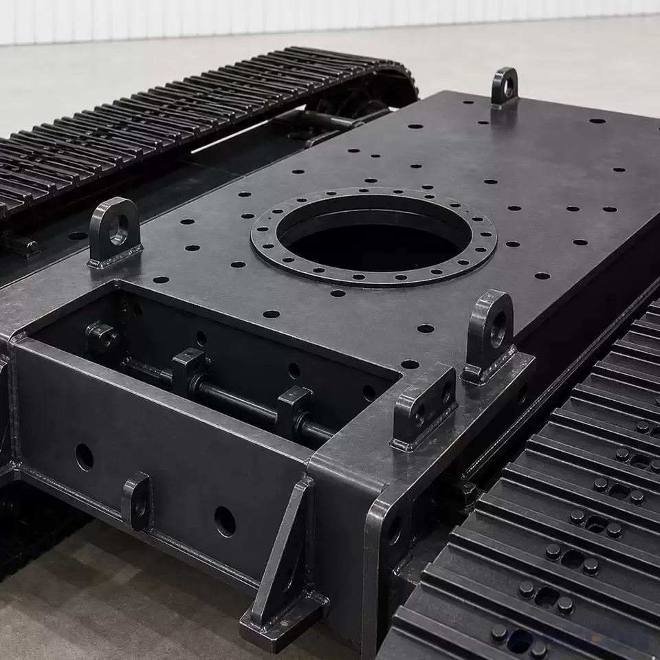
Mounting information deserves the same discipline. A phrase such as crawler undercarriage mounting dimensions may point to a valid project document, but it does not by itself indicate which values, clearances, or component relationships apply. The relevant drawing revision and the responsible technical path must be confirmed for the machine being evaluated.
Service access is another boundary to state early. It should be recorded as a project requirement, including who owns it and which controlled documentation governs it. Do not convert a general expectation about access into a claimed maintenance procedure or a promise about a particular product.
Finally, make configuration changes visible. A change to the track chain, frame layout, mounting envelope, or specified component arrangement may change the evidence that needs review. Recording the changed item, document revision, and responsible owner is more useful than relying on an earlier conversation or a generic visual.
Know When Engineering Confirmation Is Required
| Why confirmation is needed | Evidence to review | Responsible path | |
|---|---|---|---|
| Which idler and tensioning-device arrangement applies to this machine? | It is a configuration-specific structural question | Latest approved assembly or layout drawing | Engineering review against the controlled drawing set |
| Does the arrangement fit the specified track chain and frame layout? | Compatibility cannot be inferred from a generic concept | Approved technical data and project configuration records | Engineering confirmation for the project |
| What mounting boundaries or clearances apply? | These are project-specific interface facts | Approved interface drawing | Interface owner and engineering review |
| What service-access conditions must be met? | Access requirements vary by the defined project scope | Controlled requirement or service documentation | Requirement owner and engineering review |
| Does a proposed change affect the reviewed arrangement? | A change may invalidate an earlier conclusion | Current change record and affected documents |
Frequently Asked Questions
Is an idler the same thing as a tensioning device?
No. They are related in the crawler track-loop context, but they describe different roles in the discussion. The exact relationship for a particular machine must be verified from controlled project information.
Can a generic diagram confirm a final idler arrangement?
No. A generic diagram is useful only to explain a concept or relative relationship. It cannot replace an approved drawing, technical data sheet, or engineering confirmation.
What should an OEM provide before requesting a technical evaluation?
Provide the equipment and undercarriage layout, available track-loop and component information, mounting/interface documentation, current document versions, service requirements, and questions that still need confirmation. The goal is to make the evaluation traceable to the correct project version.
Should track-loop condition be discussed in the same review?
It may be relevant, but it should be kept separate from the component-identification question. The team should first define whether it is reviewing layout, configuration evidence, or the operating topic of crawler track tension.
What happens if the available drawing is outdated?
Treat it as a context document, not as final authority. Ask for the latest approved revision and review any recorded changes before drawing a project-specific conclusion.
Can MAGEON confirm compatibility from a part name alone?
No project-specific compatibility conclusion should be made from a part name alone. Provide the controlled equipment, layout, interface, and version information needed for a technical evaluation.
Prepare a Traceable Technical Evaluation
Please leave your customization requirements, and we will contact you as soon as possible!
Leave your requirements, we'll get back to you within 24 hours.