
How Should You Choose a Crawler Carrier Undercarriage?
Choose a crawler carrier undercarriage by identifying the condition that places the strongest constraint on the machine. In most projects, that constraint comes from one of four places: the load state, the ground condition, the available machine layout, or the drive and mounting arrangement.
This does not produce a final undercarriage specification from a single chart. It gives the equipment team a clear selection direction: what must be reviewed first, what can wait, and what information is still needed before a final technical evaluation.
The basic sequence is simple:
1、Define the load state the carrier must support.
2、Define the terrain the carrier must cross.
3、Check whether the upper structure, drive, and mounting areas can be packaged with the selected direction.
4、Use the result to prepare a drawing-based technical evaluation.
Start With the Condition That Drives the Decision
Do not begin with a generic preference for a wide, long, or heavy-looking track frame. Begin with the operating condition that could invalidate a concept later. For a crawler carrier, the most useful early question is: what changes when the carrier is loaded and moving in its real environment?
The table below turns that question into a practical review priority. It does not state a final performance result; it identifies the part of the selection that needs evidence first.
| First review priority | Why it matters | What still needs confirmation | |
|---|---|---|---|
| Load is mainly centered and the route is firm and level | Basic carrier layout and duty boundary | Establishes the starting configuration direction | Actual load states, route duty, and available layout data |
| Load can be offset from the carrier centerline | Load distribution and upper-structure mounting review | The working load may change the integration questions across the track frame | Center-of-gravity information and structural load path |
| Ground is soft, uneven, or changes frequently | Ground contact, clearance, and protection review | The operating surface becomes a primary constraint | Surface description, obstacles, grades, and duty pattern |
| Packaging space or drive location is fixed | Layout, drive, and interface review | A suitable concept can still be impossible to integrate |
This is the article's central point: the “best” undercarriage direction depends on the dominant condition, not on one isolated feature. A carrier may have a demanding ground condition but a simple load state, or a mild route but an offset working load and tightly fixed packaging. Those cases should not start from the same review priority.
Use a Four-Condition Matrix to Set the Review Priority
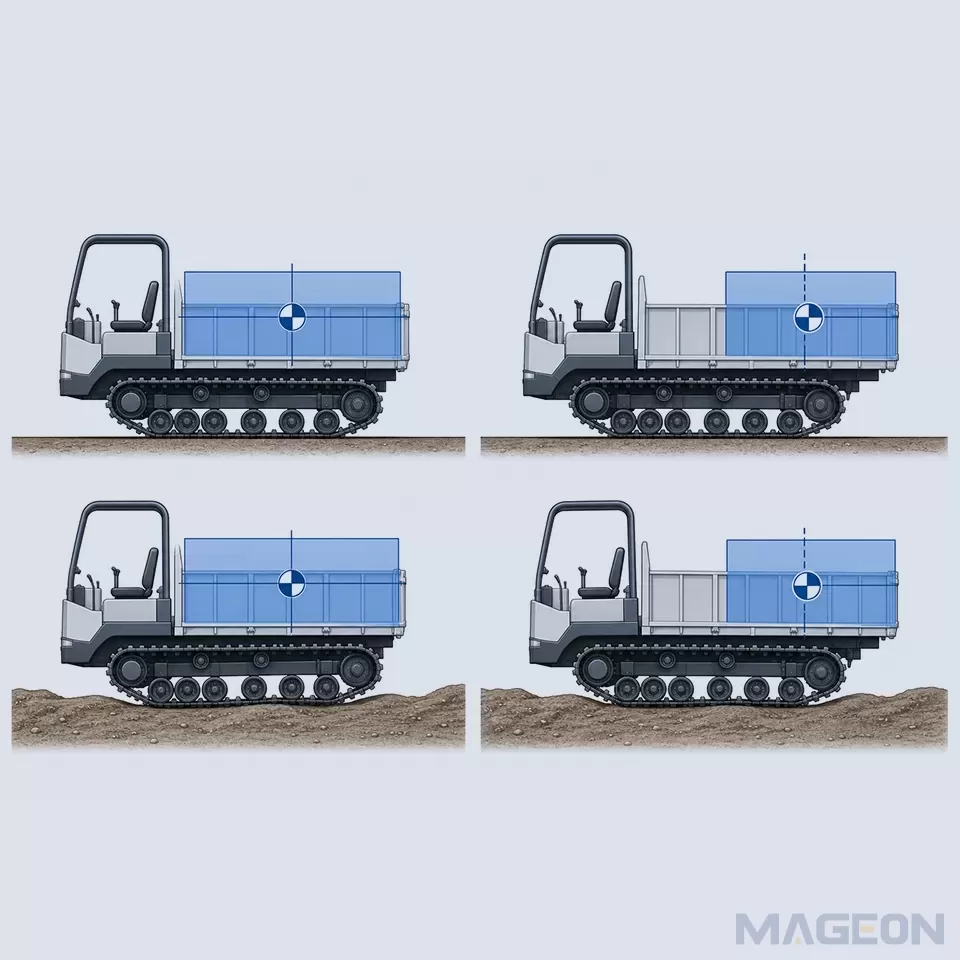
The first image compares the same generic carrier in four conditions: centered or offset load, each on firm or uneven ground. It is not a performance chart. It shows why changing either the load position or the ground condition changes the questions that need to be answered before selection can move forward.
Read the four conditions as a review guide:
Centered load on firm ground: establish the normal duty and layout boundary first. This is often the baseline condition for comparing later requirements.
Offset load on firm ground: move load distribution and mounting review forward. The key question is how the working condition relates to the upper structure and track-frame integration.
Centered load on uneven ground: move ground-contact, clearance, and protection questions forward. The load may be straightforward, but the route is now a selection driver.
Offset load on uneven ground: treat both the load state and the ground condition as decision-driving inputs. Do not reduce the review to only one of them.
The image is deliberately non-numeric. It cannot determine load capacity, stability, traction, ground pressure, or a final configuration. Those conclusions require the actual equipment data and engineering review. Its role is to prevent a team from overlooking the condition that should govern the next technical conversation.
Step 1: Define the Load State, Not Only the Payload Name
“Payload” is not yet a usable selection input if it does not describe where the load sits and when it changes. Identify the carrier conditions that matter: empty transport, normal working state, any offset or concentrated load state, and any condition that moves the center of gravity relative to the undercarriage.
For each condition, record what is known and what is only assumed. A preliminary layout may be enough to start a discussion, but it should be marked as preliminary. Do not convert an unknown center-of-gravity location into an assumed final placement just to complete a comparison.
The output of this step is a clear statement such as: “The normal operating load is the baseline, but an offset working condition requires separate mounting and load-distribution review.” That is a decision direction, not a claimed rating.
Step 2: Classify the Travel Environment by Its Constraint
Terrain should be described by the condition that changes the undercarriage review, not by a broad phrase such as “outdoor use.” Confirm whether the route is mainly firm and prepared, soft or loose, uneven, obstacle-prone, or subject to frequent transitions. Also record the travel pattern: long straight travel, repeated turns, stops, grades, or short transfers between work areas.
This information helps determine which questions move to the front of the review:
1、Firm, predictable ground keeps the emphasis on the overall carrier layout and duty definition.
2、Soft or uneven ground makes contact, clearance, and protection questions more important to clarify.
3、Repeated changes in surface or route condition mean the stated duty pattern must be reviewed instead of assuming one representative surface.
These are review priorities, not automatic answers. No terrain description alone proves a universal capability or permits a numerical performance conclusion.
Step 3: Confirm That the Direction Can Be Packaged Into the Machine
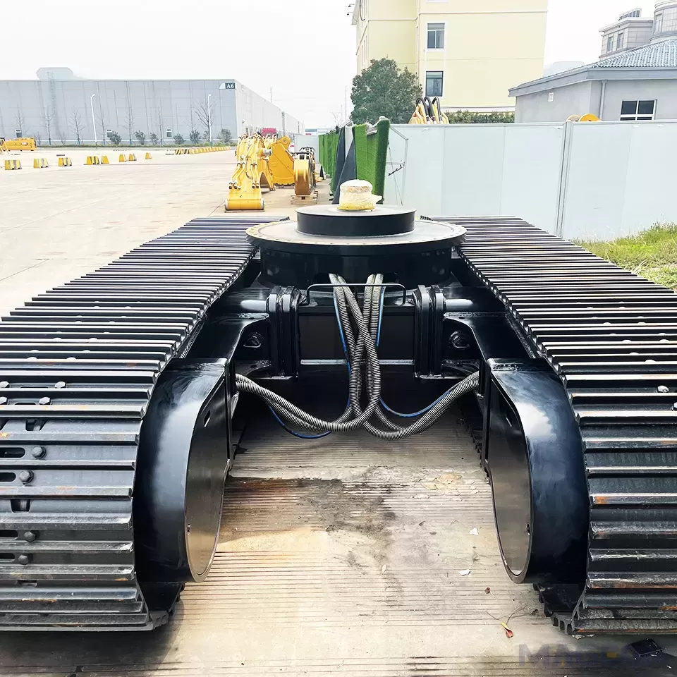
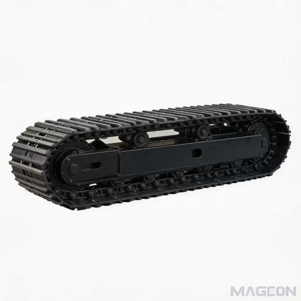
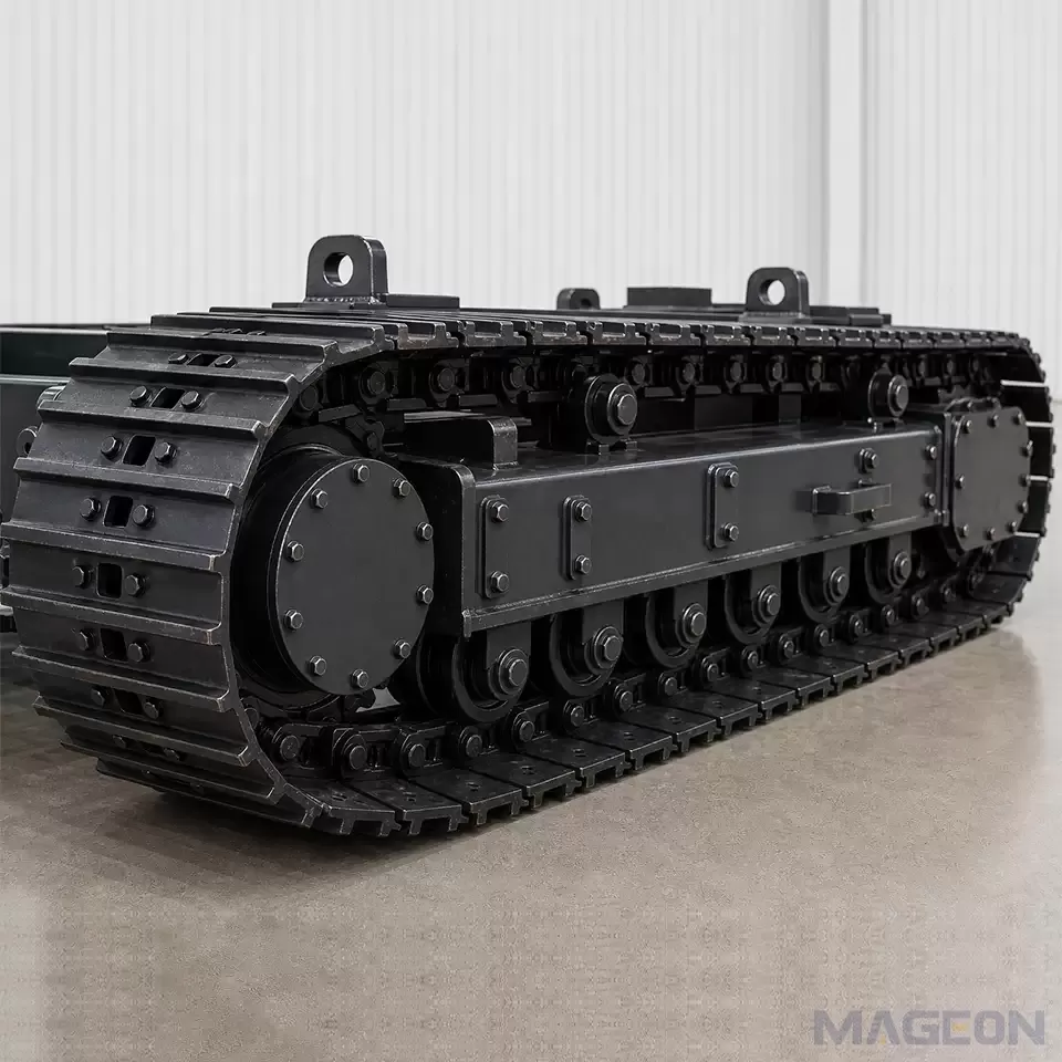
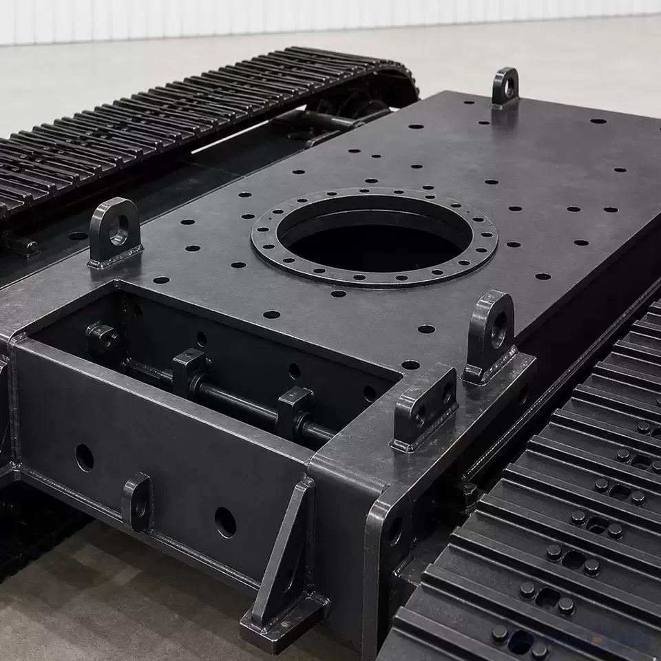
Once load and terrain establish the review priority, test the machine layout. The upper structure needs an available envelope, the travel drive needs a defined location, and the mounting areas must transfer the intended loads through an actual interface concept. Track gauge is one layout variable that should be reviewed with the carrier envelope rather than treated as a stand-alone selection answer. If any of these boundaries is fixed, it can become the dominant constraint even when the operating terrain is straightforward.
At this stage, inspect three zones together: the upper-structure packaging envelope, the drive-side area, and the mounting-interface regions. The review must be based on the actual equipment layout and interface information, not on a generic concept image or an assumed fitment.
Mounting interfaces should be identified before fitment conclusions are made. Use this check to answer three direct questions:
| What to review | Decision effect | |
|---|---|---|
| Does the upper structure have a fixed envelope? | Clearance, component positions, service access, and protected zones | May limit the usable undercarriage arrangement |
| Is the drive-side location already fixed? | Drive placement, connection path, and related space needs | May determine which end or area requires detailed integration review |
| Are mounting regions known? | Interface locations, structure, and load path |
If one of these answers is unknown, keep the selection result at “direction for evaluation.” Do not present a generic carrier illustration as evidence of verified fitment.
Step 4: Turn the Result Into a Technical Evaluation Request
At this point, the team should be able to make a short, useful statement:
The primary selection driver is [load state / terrain / packaging / drive and interfaces]. The next review must focus on [specific condition]. Final fitment or performance conclusions require [missing drawing, load, or duty information].
That statement is much more useful than sending a general product inquiry. It tells the technical team what needs attention first and makes missing inputs visible.
For a complete crawler undercarriage assembly evaluation, prepare the following:
| Minimum useful content | |
|---|---|
| Carrier application | What the carrier does and where it travels |
| Load states | Normal and exceptional working conditions, with available center-of-gravity information |
| Terrain and duty | Ground condition, route features, operating pattern, and known obstacles or grades |
| Layout | General arrangement, fixed upper-structure boundaries, and available space |
| Drive and mounting |
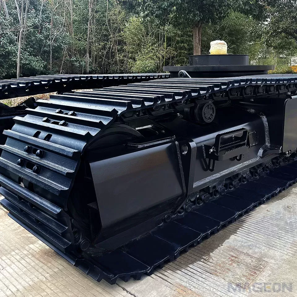
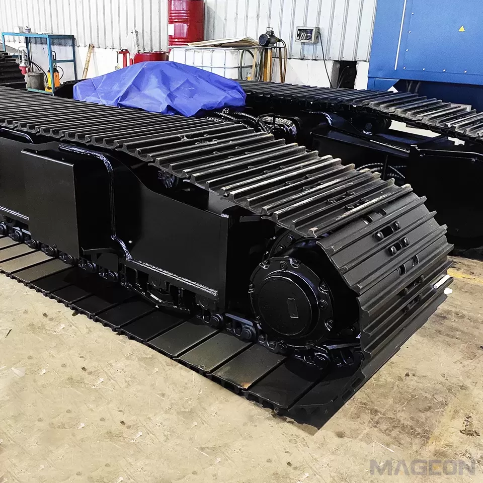
MAGEON supplies complete crawler undercarriage assemblies. Equipment, load, dimensional, and duty-condition information can be used to begin a technical evaluation. Final configuration, dimensions, and performance-related conclusions must remain subject to the current approved drawings, specifications, and engineering confirmation.
Frequently Asked Questions
Which factor should be checked first: load or terrain?
Check the one that creates the strongest constraint in the actual operating condition. If the load is offset, load distribution may lead the review. If the route is soft or uneven, terrain may lead it. When both change the result, review them together.
Can I select an undercarriage from the carrier's overall weight alone?
No. Overall weight does not describe load position, ground condition, duty pattern, packaging limits, or mounting interfaces. It is only one part of the input set.
What does “selection direction” mean?
It means identifying the next engineering priority: for example, load distribution, ground contact, layout clearance, or interface fitment. It is not a final rated configuration.
When is a layout drawing needed?
It is needed when packaging, drive placement, or mounting interfaces affect the decision. A preliminary drawing is useful if it is clearly identified as preliminary.
When can the final configuration be confirmed?
Only after the relevant equipment, load, dimensional, duty, and interface inputs are available for technical evaluation and are confirmed against current approved engineering information.
Next Step
Start by identifying the carrier's dominant selection condition. Then prepare the associated load, terrain, layout, drive, and mounting information for a technical evaluation of a complete crawler undercarriage assembly.
Please leave your customization requirements, and we will contact you as soon as possible!
Leave your requirements, we'll get back to you within 24 hours.