
How Does Track Roller Layout Affect Crawler Undercarriage Load Paths?
Track roller layout affects a crawler undercarriage by locating the support points around the track loop. In concept, the machine and track frame are supported through the lower track rollers into the lower track run and ground-contact system; carrier rollers support and guide the upper return run between the end components. The layout is therefore part of the complete undercarriage load path, not a choice that can be made from roller count, visual symmetry, or a copied arrangement alone.
The article does not prescribe a roller number, spacing, size, capacity, or service life. Those outcomes require approved drawings and project-specific engineering. Its purpose is to show OEM teams which relationships and inputs should be reviewed before they request or evaluate a crawler undercarriage direction.
Trace the Conceptual Load Path Before Reviewing Layout
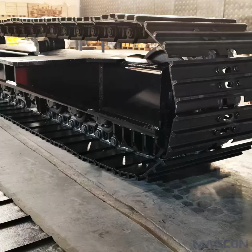
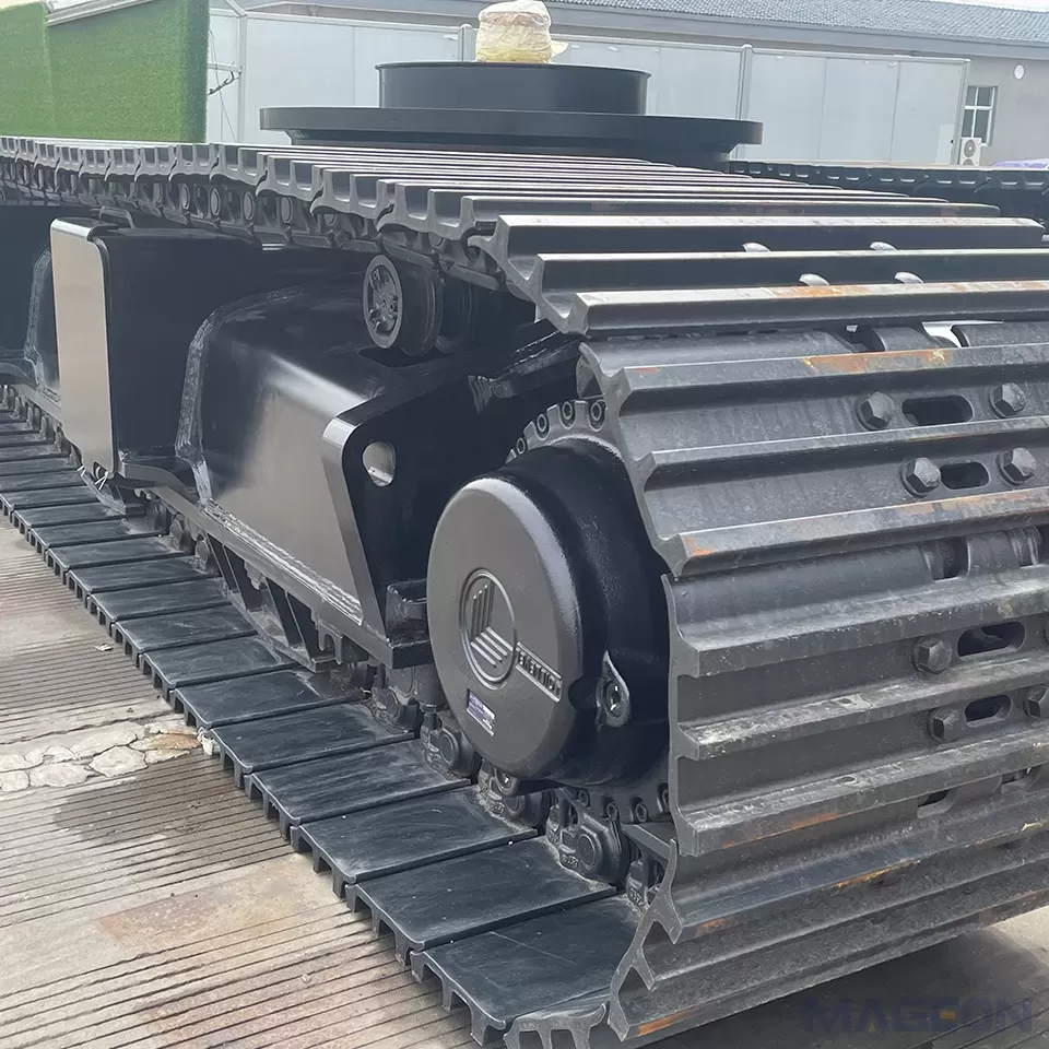
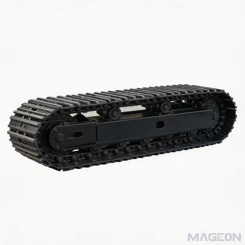
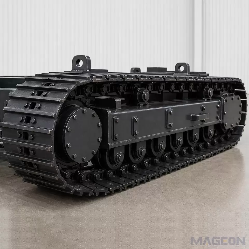
In a conceptual side view, the track frame provides the undercarriage structure. Lower track rollers sit below it and support the lower run of the track assembly. The track assembly then forms the ground-contact interface. At the ends of the loop, the drive sprocket drives the track assembly and the idler guides it; carrier rollers support the upper return run between them. Caterpillar similarly describes carrier rollers as supporting and guiding the upper portion of the track chain between the sprocket and front idler. Cat carrier roller group
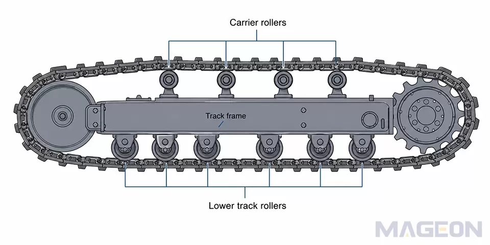
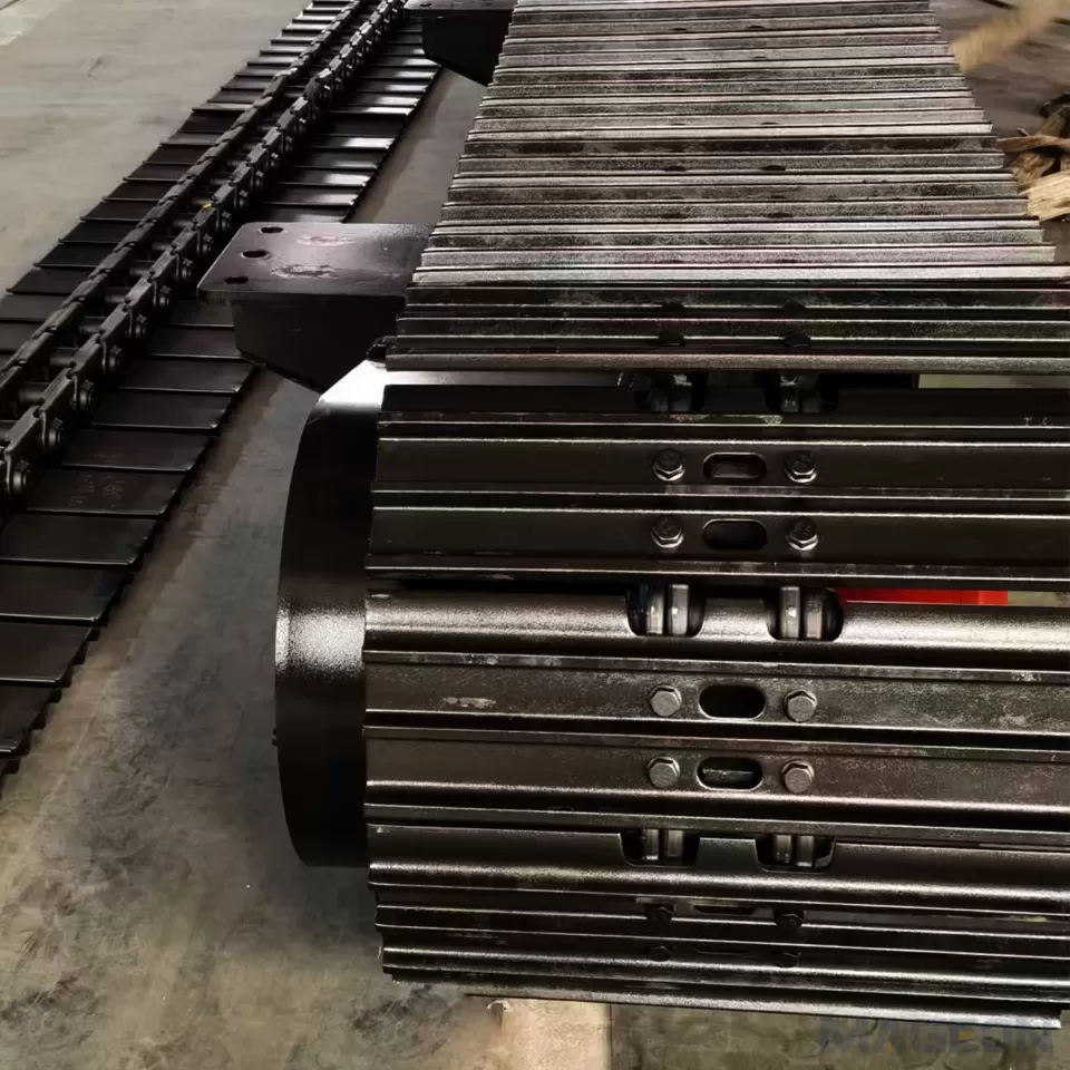
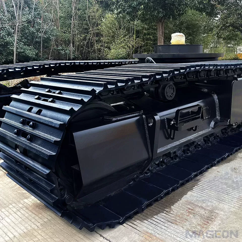
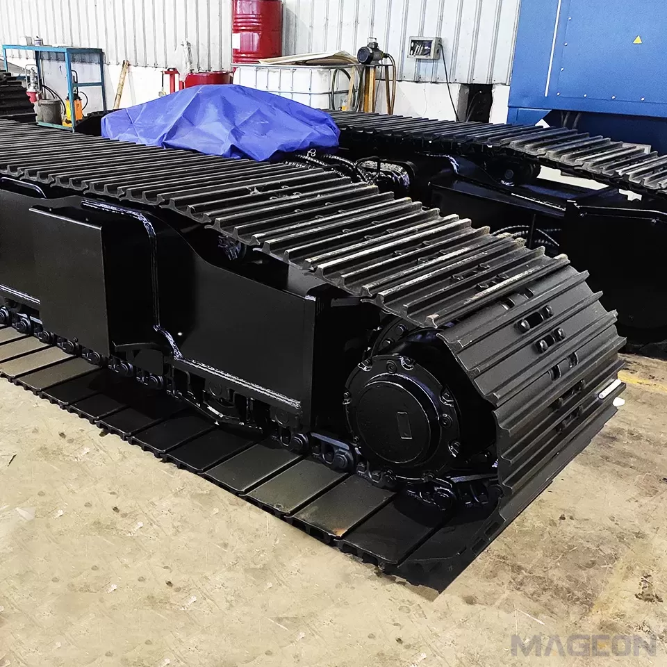
This illustration is a component-location schematic only. It shows the track frame, lower track rollers, carrier rollers, end components, and continuous track assembly as one generic system; it does not define a production roller count, an end-wheel orientation for a specific model, or an engineering load distribution.
The point is not to infer a numerical force distribution from a diagram. It is to make the role of each support path visible: lower rollers are associated with the supported lower run and ground-contact side of the system, while carrier rollers manage the upper return run. A generic equipment specification may list these components separately, but the project evaluation still needs the complete machine configuration, relevant load states, and intended duty conditions.
What Changes When the Layout Changes?
Changing a roller layout changes the locations and relationships that engineering must review. It does not, by itself, prove a better or worse design. The table below keeps the distinction clear.
| Conceptual effect on the track system | Engineering question created | What cannot be concluded from the layout alone | |
|---|---|---|---|
| Lower track-roller positions | Establish the support locations below the track frame along the lower run | Are the track-frame interfaces, lower-run support relationship, and intended ground-contact arrangement coherent for the machine states? | Exact load sharing, roller size, spacing, capacity, or life |
| Carrier-roller positions | Establish where the upper return run is supported and guided between the end components | Does the upper-run path remain compatible with the selected track system, machine packaging, and duty conditions? | A universal carrier-roller count or a guarantee of smoothness or wear life |
| Sprocket and idler relationship | Closes the continuous track loop at the drive and guiding ends | Are the drive, idler, track chain, tensioning arrangement, and frame layout being reviewed as one system? | Fitment, alignment, or tension acceptance without current technical data |
| Track-frame integration | Connects roller supports and end components to the machine-side structure | Which interfaces and relevant load states require drawing-based confirmation? |
This is the direct answer to the title: roller layout affects the load-path review by changing the system's support-point map. It changes what must be checked between the machine, frame, track loop, and ground—not a published performance result.
Start With Machine States, Not Roller Count
Begin with the states the machine is expected to encounter: equipment configuration, attachment condition, relevant load states, centre-of-gravity information, terrain, surface condition, travel and work cycle, and packaging constraints. Each input can change which undercarriage questions must be checked, even when the visible machine category appears similar.
ISO 16754:2008 illustrates why a single output cannot stand in for operating conditions. It states that actual ground-contact-pressure values can vary with load, centre-of-gravity position, terrain, track-shoe type and size, and surface conditions; its average value is intended only for comparing machine models. ISO 16754:2008 The same caution is useful here: a roller-layout discussion needs the operating context before it can support project-specific engineering.
| Confirm before review | Load-path question it informs | What it does not determine alone | |
|---|---|---|---|
| Machine and attachment states | Configuration, relevant load states, and centre-of-gravity information | Which machine states need separate engineering review | A final roller count or layout |
| Track-frame and track-system information | Available layout, track-chain arrangement, and target dimensions | Which interfaces and packaging conditions must be checked | A final component size or spacing |
| Ground and duty conditions | Terrain, surface condition, travel pattern, and work cycle | Which operating context the evaluation must address | A guaranteed contact-pressure or wear result |
| Whole-machine integration | Drive, mounting interfaces, and upper-machine envelope | How the undercarriage must fit the complete machine |
Review Contact Length, Track Frame, and Roller Layout Together
Contact length, track-frame geometry, and roller layout should be treated as linked review subjects. The engineering question is not whether one is more important in the abstract. It is whether the proposed configuration leaves a coherent, reviewable relationship among the track frame, lower and upper track runs, lower track rollers, carrier rollers, end components, and intended ground contact.
Track gauge is another layout input that should be reviewed with the machine envelope rather than added after a roller direction is assumed. Likewise, crawler track tension belongs to the complete track-system conversation; it is not a substitute for validating the intended machine layout and duty conditions.
When an OEM compares two preliminary directions, the useful comparison is a question set: what changes in the complete machine, what remains fixed, which load states are relevant, and what evidence is available? This approach makes it possible to separate a concept discussion from a design-ready conclusion.
Prepare the Inputs for Project-Specific Engineering Review
The first engineering package should describe the machine and the expected use, not merely request a particular number of rollers. Provide the information below together and record what remains open.
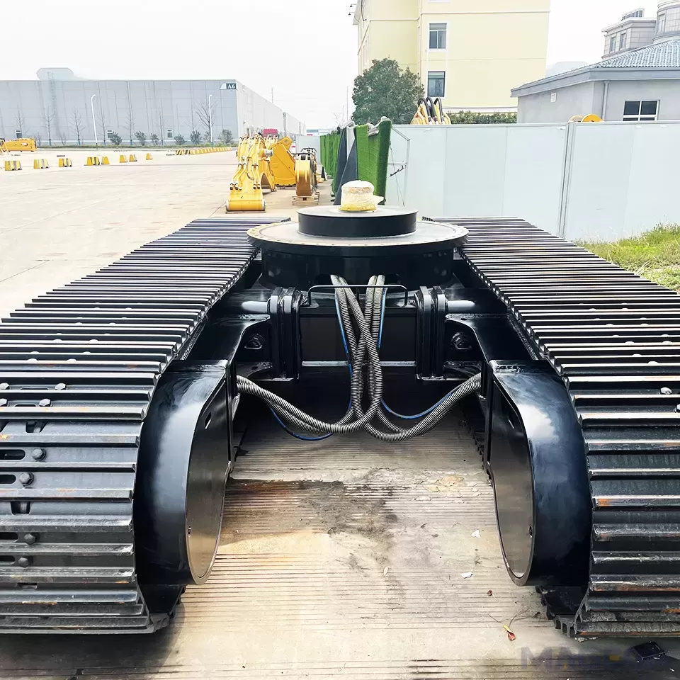
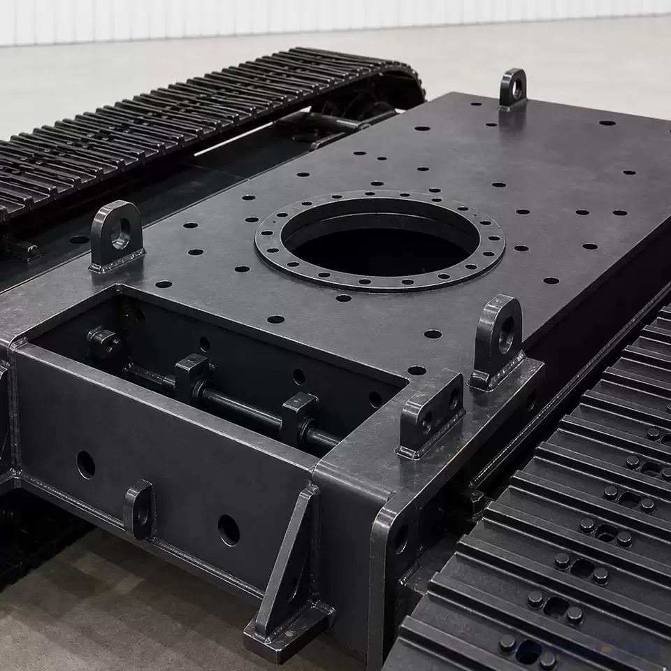
Mounting interfaces should be identified from the current machine information before fitment conclusions are made. They connect the track-frame discussion to the upper machine, drive arrangement, and packaging boundary; they are not a final approval of compatibility by themselves.
| Provide | Used to review | If unavailable | |
|---|---|---|---|
| Equipment definition | Configuration, attachments, and intended operating states | The boundary for relevant load cases | Keep the scope open; do not issue a final direction |
| Load and layout | Relevant load states, centre-of-gravity information, target dimensions, and envelope | Track-frame, roller-layout, and integration questions | Obtain approved drawings or engineering data |
| Track system | Track-chain information, track-shoe direction, and current service or duty assumptions | System-level interfaces and review conditions | Mark the input as open rather than assume equivalence |
| Duty conditions | Terrain, surface, travel and work cycle, and environment | Operating context for the engineering review | Request a defined duty description |
| Machine interfaces | Drive, mounting interfaces, and packaging constraints | Whole-machine fitment questions |
MAGEON invites OEM teams to provide equipment, load, dimensional, and duty-condition information for a project-level technical evaluation or inquiry. The resulting discussion can identify what needs engineering confirmation; it does not replace that confirmation.
Frequently Asked Questions
Can an OEM choose roller layout by copying a similar machine?
No. A similar external appearance does not confirm the same configuration, load states, track system, duty conditions, or interfaces. Use the other machine only as a question prompt, not as a design conclusion.
Does adding a roller automatically improve the undercarriage?
No. A component-count change is not a complete engineering answer. The relevant machine state, track-frame relationship, track system, and duty conditions must be assessed together.
Is track roller layout the same as track tension?
No. Roller layout is one part of the undercarriage load-path discussion; track tension is a separate track-system condition. Neither replaces whole-machine engineering review.
What do carrier rollers add to the layout discussion?
Carrier rollers concern the upper return run, not the lower ground-contact support path. They should be reviewed with the track assembly, sprocket, idler, track frame, packaging, and duty conditions; their presence alone does not establish a roller count, alignment result, or service-life outcome.
What should be available before a project-specific conclusion is made?
Current equipment configuration, load and centre-of-gravity information, dimensions, track-system details, duty conditions, drive requirements, and mounting-interface data should be available for engineering review.
Can a published roller layout establish component life or a maintenance interval?
No. A public layout image or article does not establish component life, service interval, or maintenance outcome. Those conclusions require the applicable project information, operating conditions, and approved technical evidence.
Please leave your customization requirements, and we will contact you as soon as possible!
Leave your requirements, we'll get back to you within 24 hours.