
How Do Obstacles, Ramps, and Transition Angles Affect Crawler Undercarriage Requirements?
Obstacles, ramps, and abrupt terrain transitions affect more than ground clearance. They change where the machine is supported, how the body pitches, which parts of the machine envelope approach the ground, and what traction, drive, braking, and structural loads may occur during the maneuver. Crawler undercarriage obstacle clearance is therefore a whole-machine requirement, not a single undercarriage dimension.
An OEM should first define the terrain profile and the machine state in which it must be crossed. The design team can then check geometry, examine relevant load cases, and choose an appropriate verification method. A universal obstacle height or ramp angle is not reliable because the result depends on the machine layout, center of gravity, operating load, attachments, travel direction, speed, surface conditions, and acceptance criteria.
Define the Terrain Profile Before Discussing Capability
“Uneven ground” is too vague for an engineering review. A vertical curb, a rounded ridge, a trench, a continuous ramp, a sharp crest, and a concave transition create different contact sequences. The input should describe the actual path the machine must negotiate, including any edge radius, surface change, or restricted approach direction.
Historical U.S. Army Test and Evaluation Command procedures treated bridging, wall climbing, trench crossing, and loading-ramp evaluation as distinct tests. A later procedure likewise defined gap-crossing and wall-climbing capability under controlled obstacle conditions. These documents are military and historical, so they are not sources of modern commercial limits, but they demonstrate why a test profile must be defined before a capability result has meaning. (Standard Obstacles; Tracked Vehicle Obstacles)
| Input to record | Why it matters | Confirmation source | |
|---|---|---|---|
| Step, curb, or ridge | Height, edge shape, width, and approach direction | Defines the initial contact and body-pitch sequence | Dimensioned site profile or project specification |
| Gap or trench | Width, depth, edge condition, and support on both sides | Changes the available support under the tracks | Survey, drawing, or controlled test fixture |
| Continuous ramp | Grade, length, surface, and required travel direction | Affects sustained traction, braking, and subsystem operation | Duty-condition record and risk assessment |
| Crest or valley transition | Adjacent grades, transition shape, and lowest machine points | Determines possible underside or overhang interference |
Photographs can help explain the scene, but they do not replace a dimensioned profile. The controlling input should also state whether the surface is rigid, deformable, loose, wet, contaminated, or likely to change during operation.
Check the Full Machine Geometry Through the Transition
A flat-ground clearance check is only the starting point. The machine should be reviewed through its complete path: first contact, climb, maximum pitch, crest crossing, descent, and return to level ground. At each position, the active support region and the nearest point of the machine envelope may change.
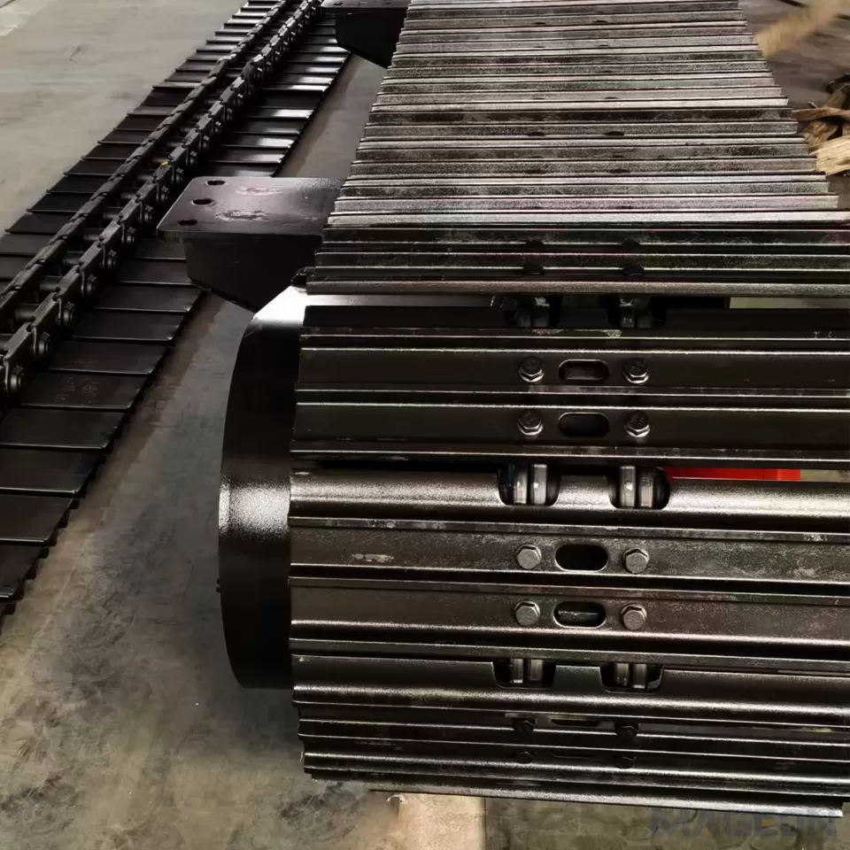
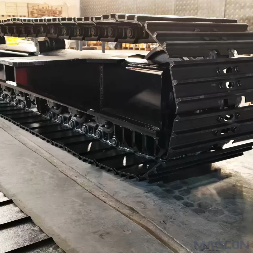
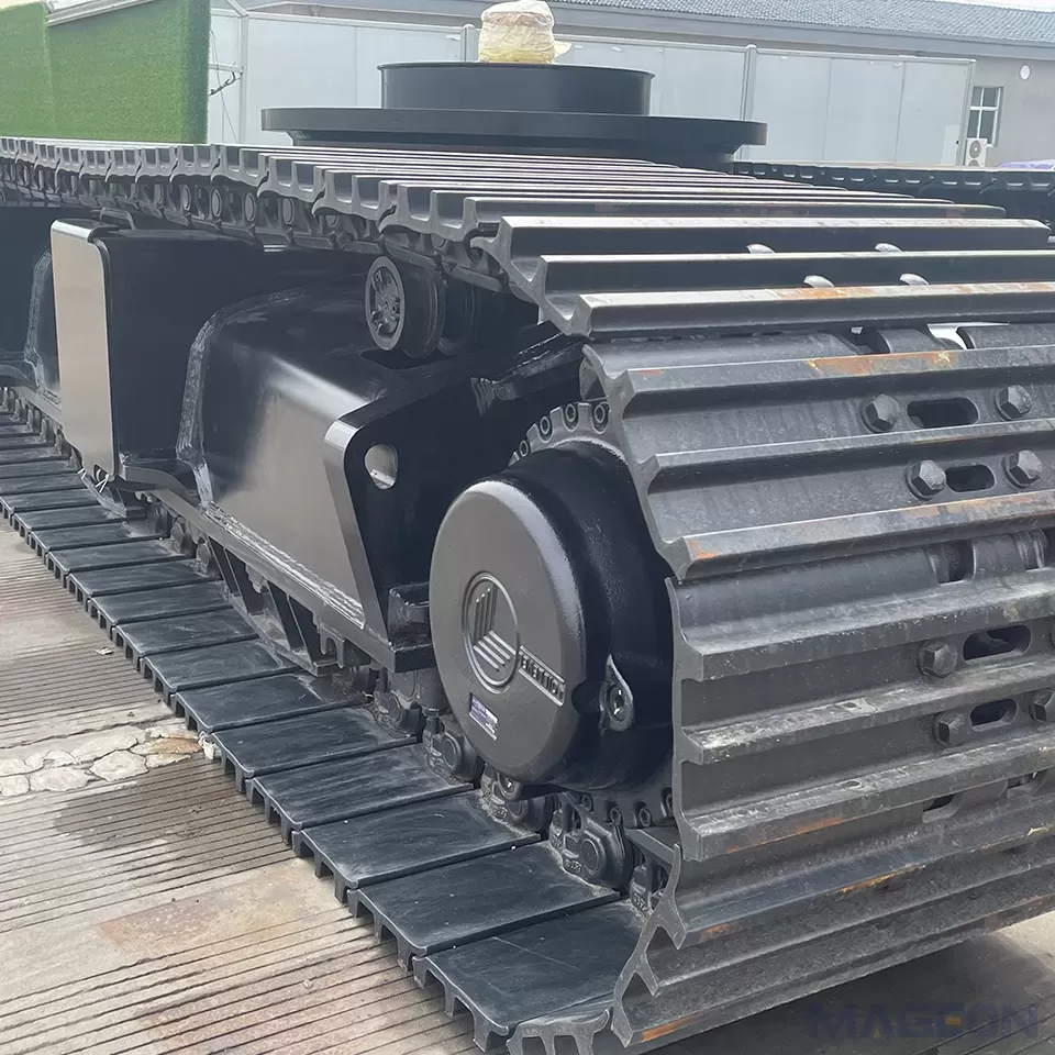
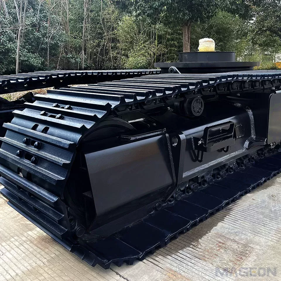
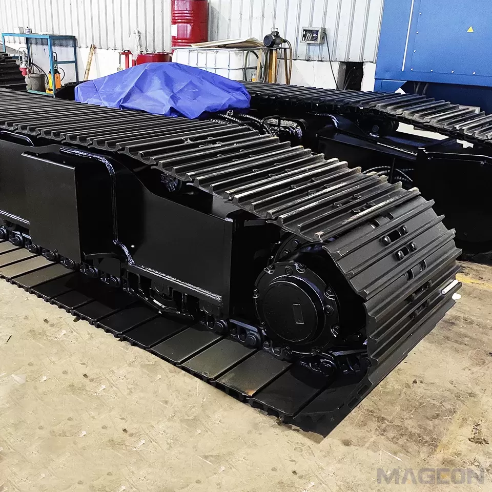
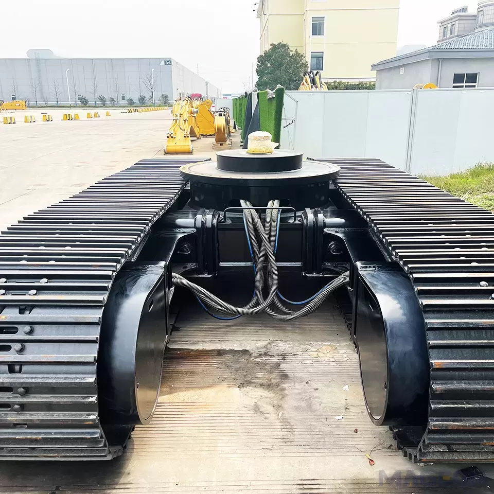
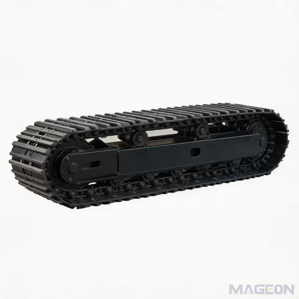
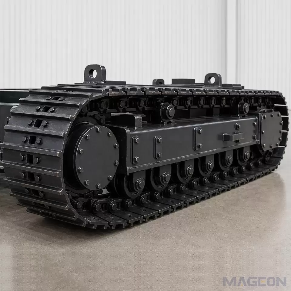
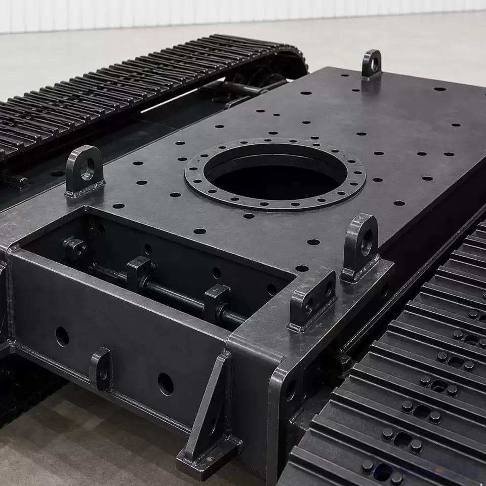
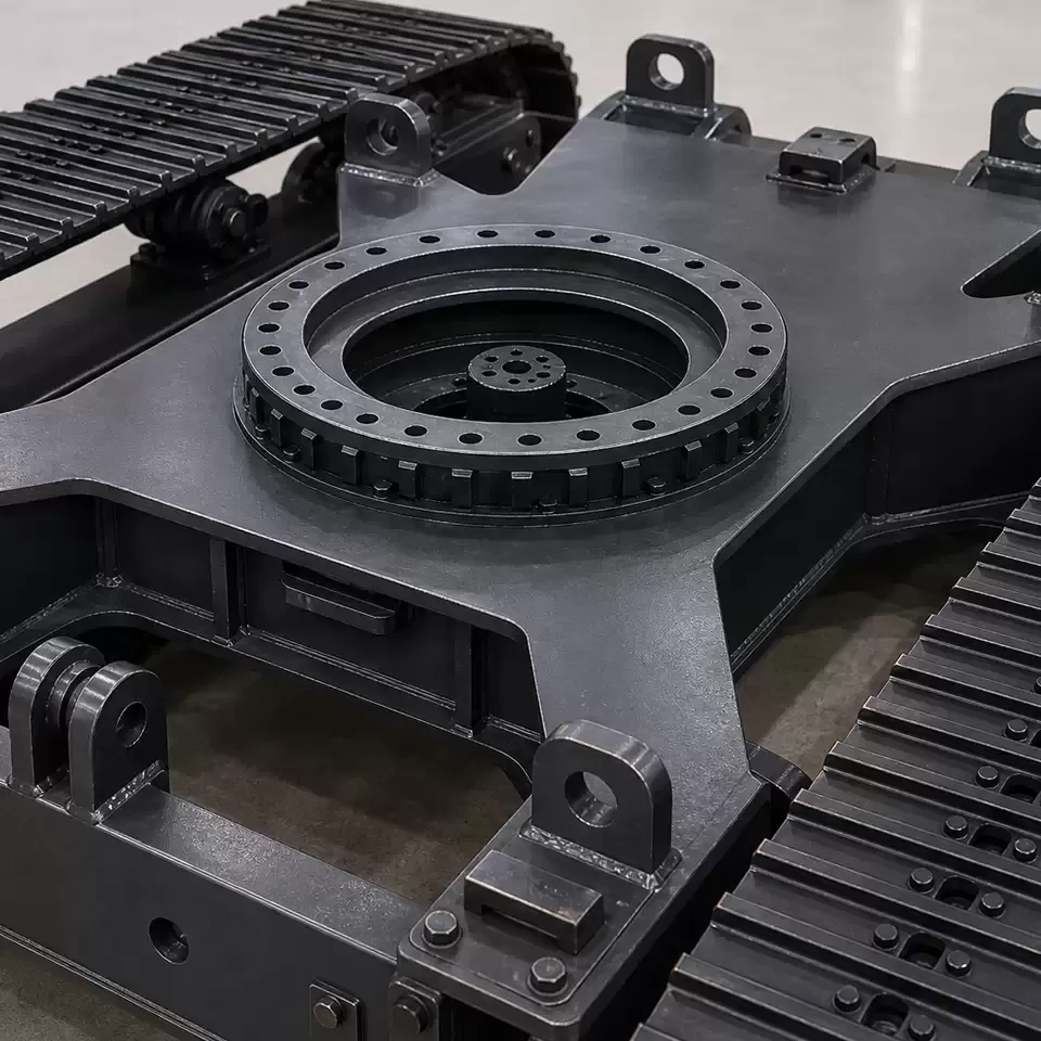
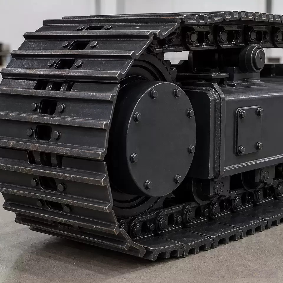
This path check should begin with the crawler undercarriage mounting dimensions, but it must continue through every machine position that occurs during the transition. Relevant inputs include the front and rear track geometry, track-on-ground length, underbody profile, structural cross-members, attachment overhang, hose or cable protection, and any component that moves relative to the chassis.
ISO 6746-1:2003 defines a reference system and codes for dimensions of earth-moving base machines and was confirmed again in 2026. It can support consistent dimensional language, but it does not provide a project-specific obstacle limit. The OEM still needs the approved machine layout and the applicable operating configuration.
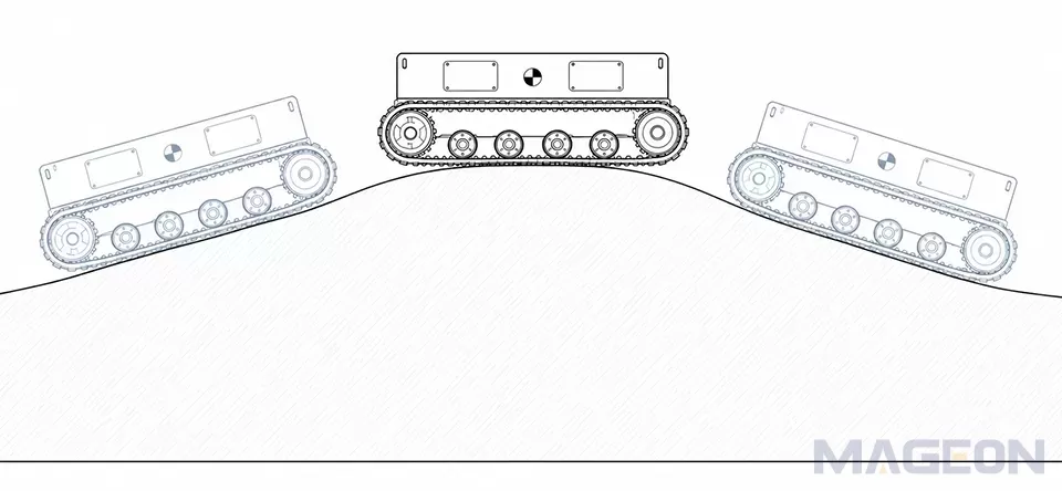
Approach, departure, and breakover geometry describe different parts of the path. Improving one relationship does not automatically resolve another, and a dimension that appears adequate in a static side view may not remain adequate when the track deforms, the body pitches, or an attachment changes position. The result should be checked as a motion envelope rather than as an isolated angle.
Include Load State, Speed, and Surface Conditions
The same machine can behave differently when empty, carrying its working load, or holding an attachment in another position. These states can move the center of gravity and alter how load transfers between the available support points. The crawler undercarriage track gauge is relevant to lateral stability, but it cannot by itself define whether the machine can negotiate a longitudinal crest or ramp.
Research on a tracked orchard chassis modeled and tested the relationship among the obstacle support point, center of gravity, track contact geometry, pitch, and landing behavior. Another tracked-equipment study examined approach and departure geometry together with center-of-gravity position, ground contact length, and ground conditions. Both studies used specific prototypes and assumptions; their numerical results should not be generalized, but they support the qualitative conclusion that obstacle crossing is a coupled geometry-and-load problem. (Agriculture, 2023; Applied Sciences, 2023)
Travel speed also changes the question. A slow geometric clearance check does not establish the impact, vibration, track-ground interaction, stopping, or control behavior at operating speed. Surface strength and friction affect whether the assumed support and traction are available. If these conditions are uncertain, the analysis should use bounded scenarios and the final capability should remain subject to controlled testing.
Translate Duty Conditions into Undercarriage Requirements
The OEM does not need to prescribe every undercarriage detail before consulting a supplier. It does need to provide enough information for the supplier and whole-machine team to identify the affected decisions.
| Potential effect | Engineering question | Verification path | |
|---|---|---|---|
| Terrain profile and approach direction | Contact sequence and clearance envelope | Which machine point approaches the terrain first? | Layout sweep or kinematic check |
| Mass, center of gravity, and load state | Support reactions and pitch or stability margin | Which operating state governs the review? | Approved mass properties and load-case analysis |
| Speed, crossing frequency, and surface | Impact, traction, braking, and duty severity | Is a static check sufficient? | Dynamic analysis and controlled test as needed |
| Attachment position and machine overhang | Interference and center-of-gravity shift | Which attachment configurations must be included? |
These inputs may influence undercarriage length, front and rear geometry, support and roller arrangement, structural load paths, drive selection, braking requirements, guarding, and interface zones. They do not lead to one automatic design answer. Each decision must be coordinated with the whole machine and supported by the controlling project evidence.
A 2024 tracked-robot study treated extreme obstacle crossing as a combination of geometric, slip, stability, and drive-torque constraints and verified its model through simulation and prototype experiments. Its scale and mechanism differ from industrial OEM machines, so it should not supply design values here. It does, however, reinforce the need to evaluate several constraints together rather than optimize a single clearance number. (Robotics and Autonomous Systems, 2024)
Validate Capability Instead of Applying a Universal Limit
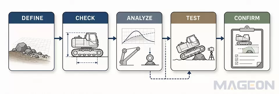
Validation should be proportional to the risk and novelty of the project. A practical sequence is:
1、Define a dimensioned terrain profile and the required machine configurations.
2、Check the whole-machine envelope through the complete transition.
3、Analyze governing mass, center-of-gravity, traction, structural, drive, and braking conditions.
4、Use contact or multibody simulation when static geometry cannot represent the important behavior.
5、Run a controlled test with agreed conditions, instrumentation, acceptance criteria, and stop rules.
6、Record the verified configuration and the conditions outside its approved scope.
Standards can govern individual parts of this work without producing one universal slope capability. ISO 10266:1992, for example, specifies a static method for evaluating slope limits of machine fluid systems. ISO 10265:2008, confirmed in 2025, addresses braking-system performance and test procedures for crawler machines within its scope. A fluid-system static limit or a braking result is not, by itself, proof of whole-machine obstacle clearance, traction, or stability.
The project team should also check applicable safety and regulatory requirements for the machine category and destination market. This article is a design-input framework, not a substitute for a project risk assessment or engineering approval.
What OEMs Should Provide for Technical Evaluation
A custom crawler undercarriage specification should therefore include a dimensioned terrain profile and acceptance method, not only a requested obstacle height or slope.
| Required detail | Controlling evidence | Open decision | |
|---|---|---|---|
| Whole-machine layout | Lowest points, overhangs, moving attachments, and interface datums | Latest approved drawing or controlled model | Configurations to include |
| Mass properties | Operating masses, center-of-gravity states, and load cases | Approved calculation or engineering record | Governing state |
| Terrain and operation | Profile, surface, direction, speed, and crossing frequency | Project specification or measured site data | Design case and test case |
| Acceptance plan | Method, configuration, criteria, and responsibility | Approved validation plan |
The input package should identify document versions and unresolved assumptions. If the real terrain cannot be measured precisely, define a conservative test profile and state why it represents the intended duty. Avoid using an informal photograph, a competitor claim, or a single supplier brochure as the controlling acceptance basis.
Close with Engineering Boundaries and the Next Step
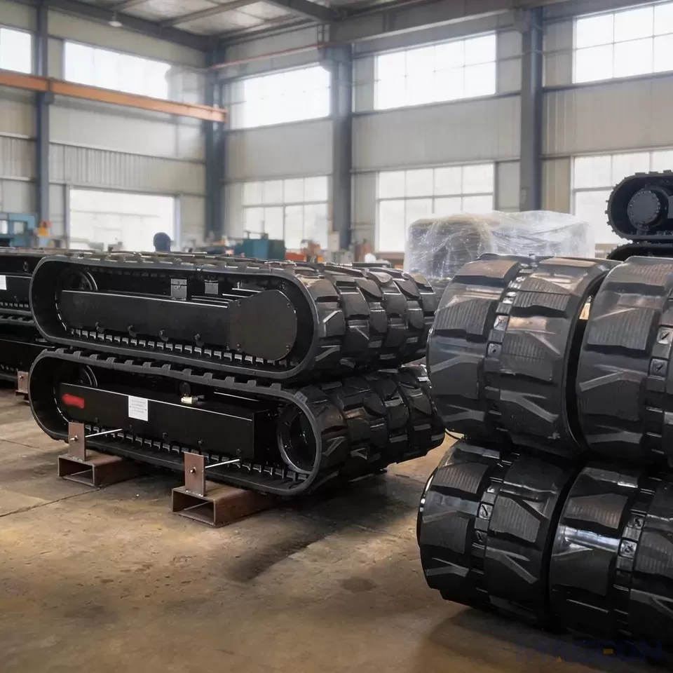
For complete crawler undercarriage assemblies, the review should connect machine geometry, operating load, travel conditions, and the agreed validation method. The reliable sequence is to define the terrain, check the full motion envelope, analyze governing conditions, and verify the result under controlled project-specific conditions.
Share your equipment layout, load information, dimensional constraints, obstacle or ramp profile, and duty conditions with MAGEON for a technical evaluation or project inquiry.
Frequently Asked Questions
Is ground clearance alone enough to predict obstacle-crossing capability?
No. Ground clearance describes only part of the machine geometry. Support location, front and rear geometry, overhangs, center of gravity, load state, surface, and travel behavior can all change the result.
Which obstacle dimensions should an OEM provide?
Provide a dimensioned profile that identifies height or depth, width, edge shape, adjacent grades, transition shape, surface condition, and approach direction as applicable. Also identify the machine configuration and load state that must cross it.
What is the difference between approach, departure, and breakover geometry?
Approach geometry concerns the front of the machine entering a rise, while departure geometry concerns the rear leaving it. Breakover geometry concerns interference near the underside as the machine passes a crest; none of these values alone confirms traction or stability.
Why does the machine load state matter on a ramp or transition?
The load and attachment position can change the total mass, center of gravity, support reactions, and required drive or braking effort. The governing operating state may therefore differ from the empty-machine condition.
Can one maximum slope value represent the whole machine?
Not reliably. Stability, traction, braking, fluid-system operation, attachment position, direction of travel, and applicable safety requirements may impose different limits. The project must identify and verify the governing condition.
When is simulation needed before prototype testing?
Simulation is useful when contact changes, dynamic loads, track-ground interaction, or multiple configurations cannot be represented by a static clearance check. Its assumptions should be documented, and safety-critical conclusions should be confirmed by an appropriate validation method.
What should be included in an obstacle-clearance acceptance test?
Define the test profile, surface, machine configuration, load state, approach direction, speed or control method, acceptance criteria, instrumentation where needed, and stop rules. Record the verified configuration so the result is not applied outside its tested conditions.
Please leave your customization requirements, and we will contact you as soon as possible!
Leave your requirements, we'll get back to you within 24 hours.