What are the structures and operating mechanisms of the excavator chassis? MAGION gives you complete technical analysis
Project Overview:
This article systematically elaborates the core structural elements and operating principles of excavator track undercarriage, covering three major components: travel system, power transmission unit and load-bearing frame. It analyzes the applicable scenarios of tracked and wheeled travel modes, and discusses the cooperative working mechanism of engine, transmission and travel motor in the drive system. The article also introduces reliability design details including surface-hardened track pins, IP67 sealed rollers and FEA-optimized welded frame, with a continuous service life of 12,000 hours and an ambient temperature adaptation range of -40°C to +50°C. It serves as a technical reference for construction machinery R&D personnel, equipment procurement teams and engineering operators.
In-Depth Analysis of Excavator Chassis Structure and Operating Mechanism
The excavator crawler undercarriage is the core load-bearing and travel system that supports the entire upper structure and realizes equipment movement. Its structural design and power transmission efficiency directly determine the equipment's operation stability, terrain adaptability and service life. As a professional undercarriage manufacturer, MAGEON systematically explains the core components, power transmission principles and technical details of the chassis in this guide, providing technical reference for the construction machinery industry.
Core Technical Parameters & Specifications
The excavator chassis system integrates multiple technical subsystems with strict performance indicators. Core parameters are summarized as follows:
| Technical Category | Key Indicators | Parameter Range / Standard |
|---|---|---|
| Travel System | Tracked ground pressure | As low as 30 kPa |
| Travel System | Wheeled minimum turning radius | 80% of body length |
| Travel System | Tracked climbing capacity | ≤ 35° slope |
| Power System | Diesel engine power range | 80 – 450 kW |
| Transmission System | Final drive efficiency | ≥ 92% |
| Transmission System | Brake torque reserve factor | 1.8 |
| Reliability Design | Track pin surface hardness | HRC 58 – 62 |
| Reliability Design | Roller protection grade | IP67 |
| Reliability Design | Frame safety factor | ≥ 2.5 |
| Environmental Adaptation | Operating temperature range | -40°C to +50°C |
| Service Life | Continuous operation life | 12,000 hours |
1. Core Component Structure Analysis
(1) Travel System
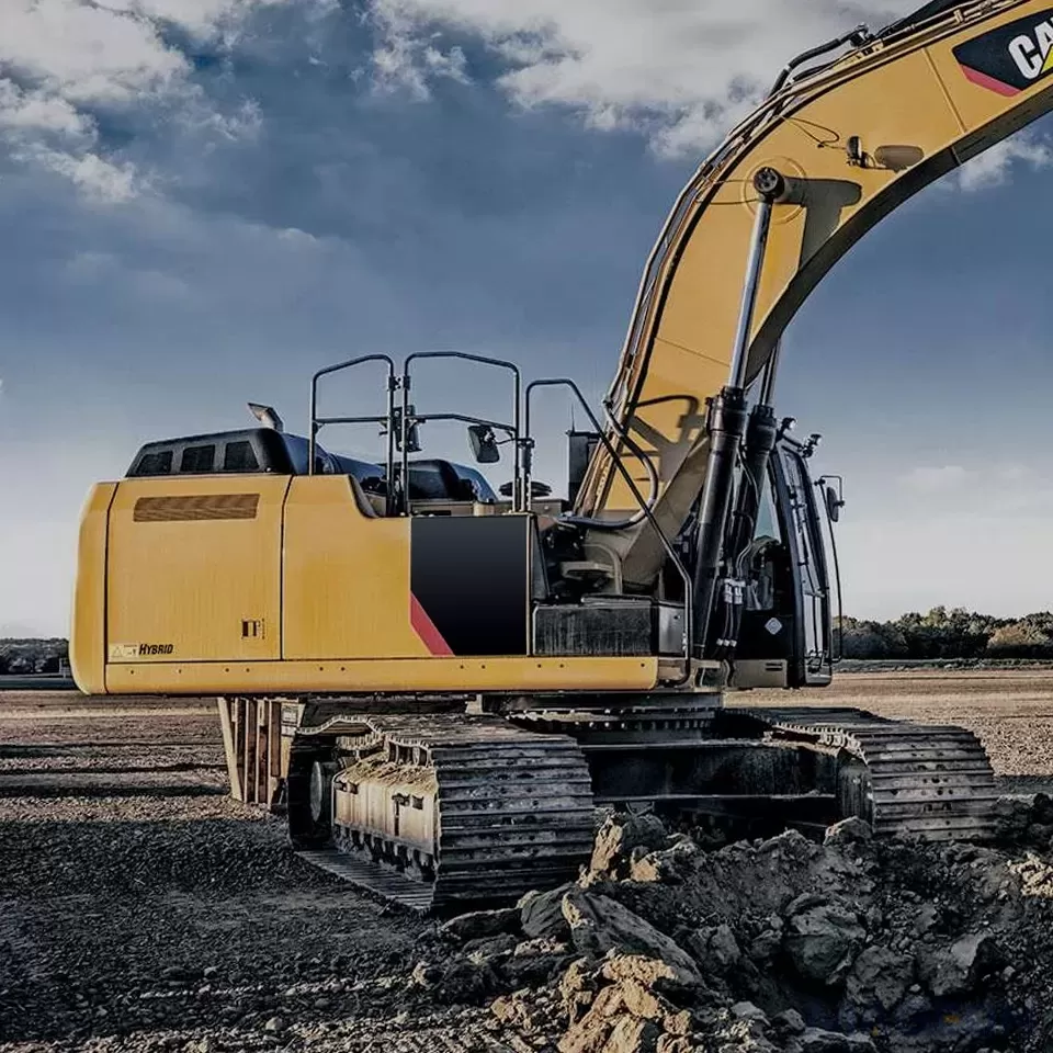
The travel system is the executive mechanism for chassis movement, divided into tracked and wheeled configurations:
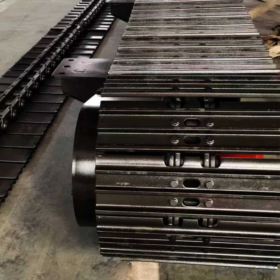
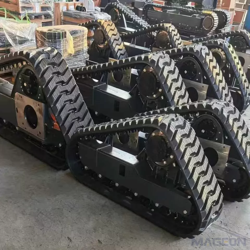
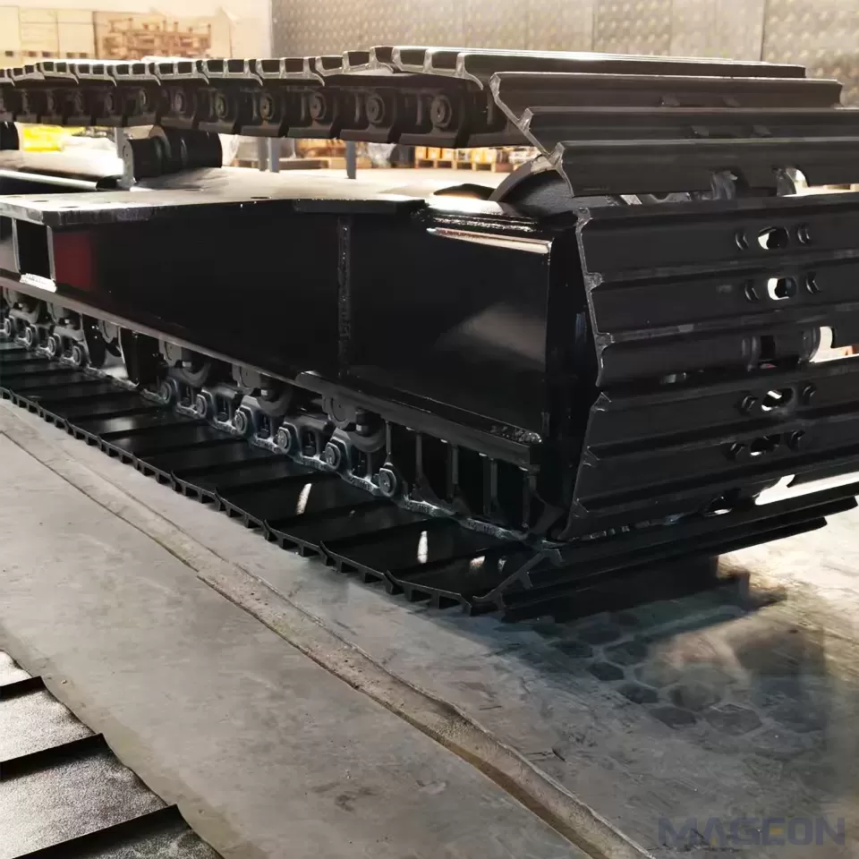
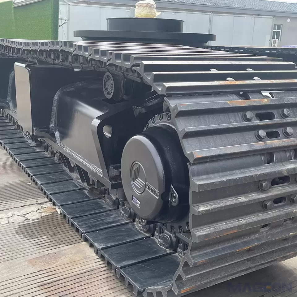
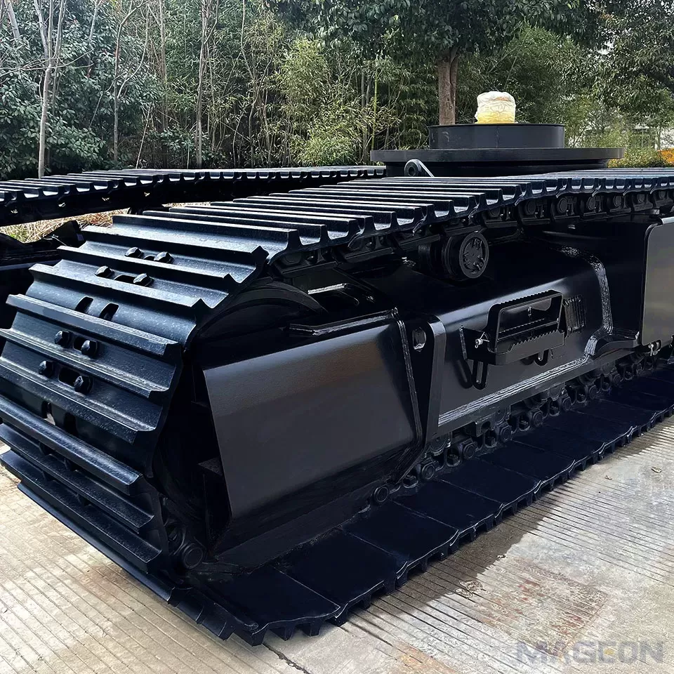
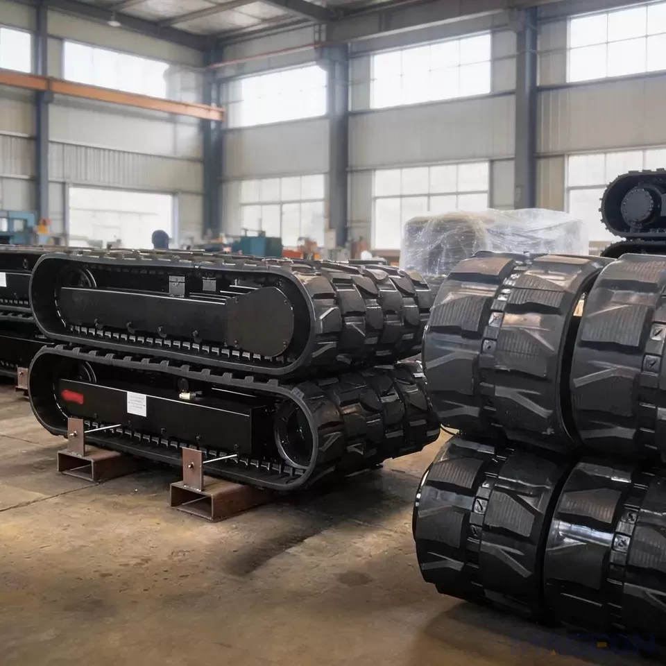
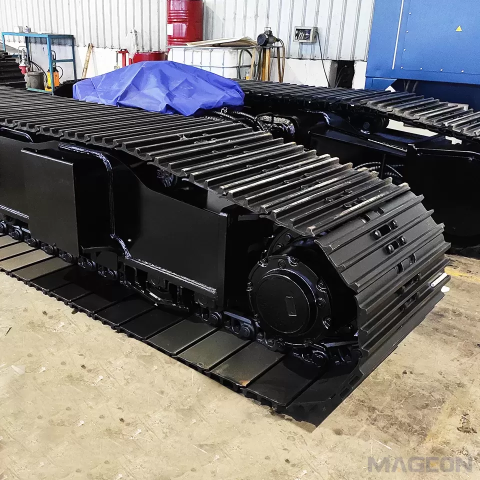
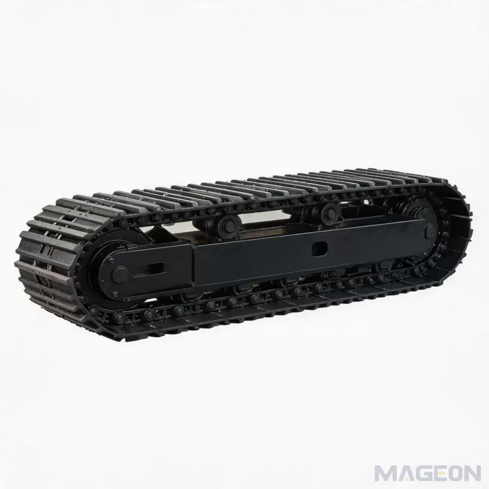
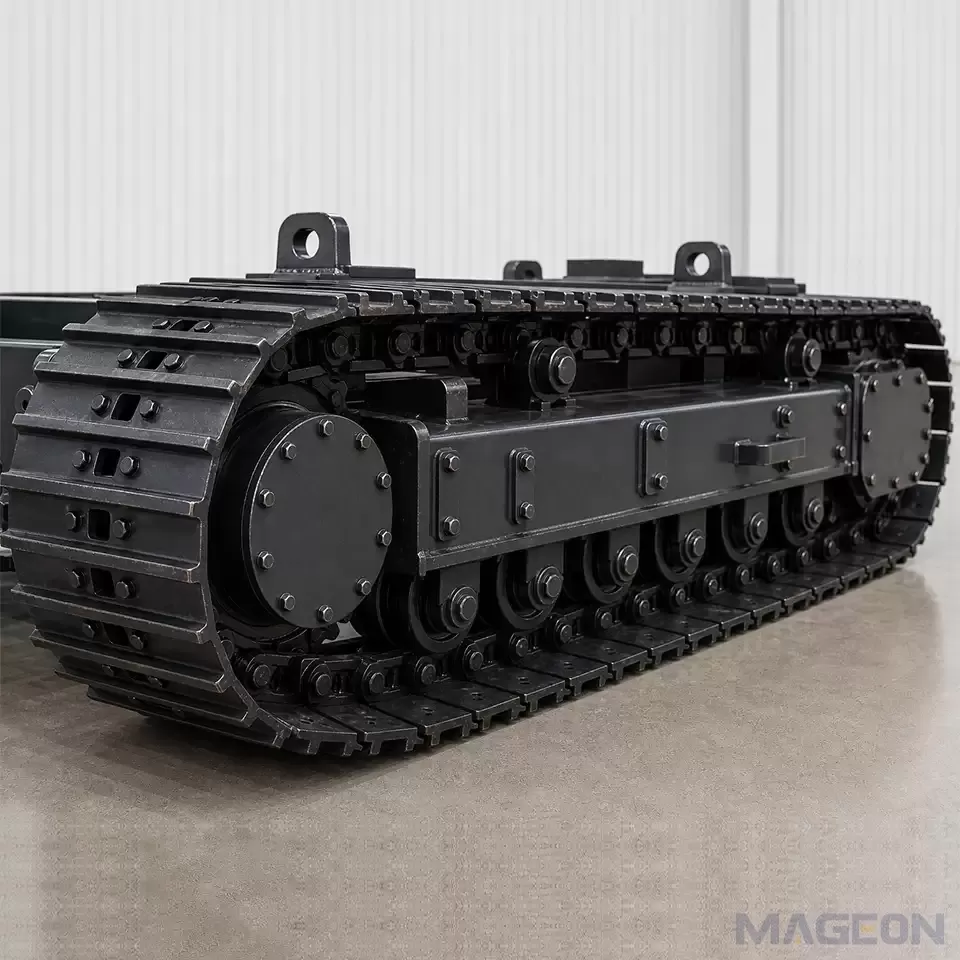
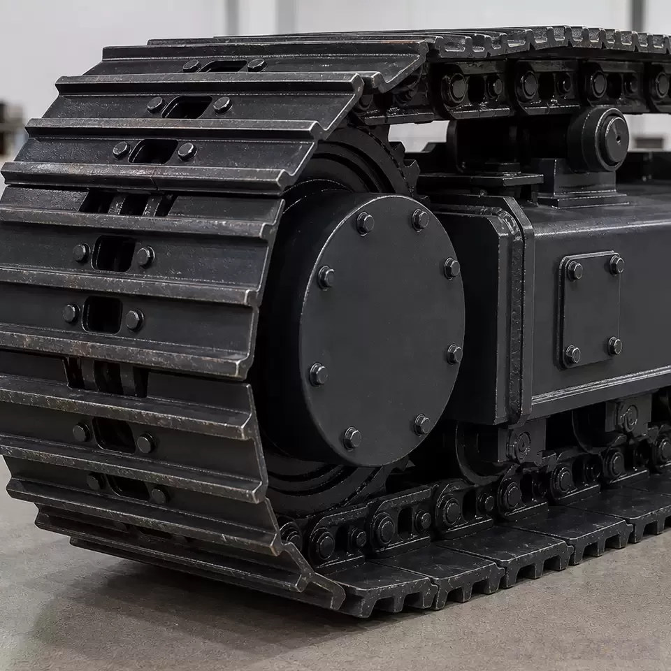
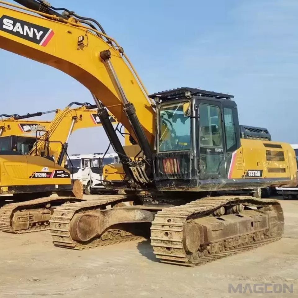
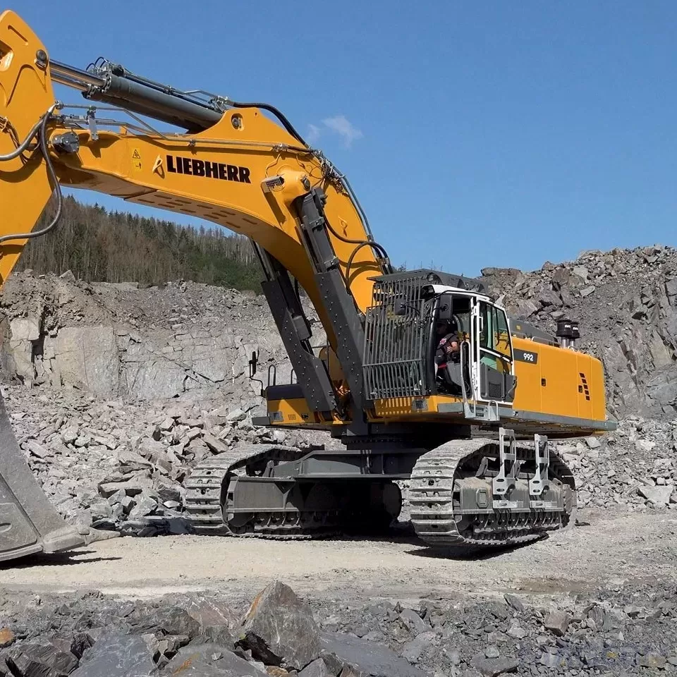
Tracked travel system: Consists of drive sprocket, idler, track assembly and guide wheels. The track assembly is composed of track links, track roller groups and side guard plates. It features low ground pressure and strong terrain adaptability.
Wheeled travel system: Adopts high-strength radial tires with counterweight structure, delivering high travel speed and good road mobility.
(2) Power Transmission Unit
The power transmission unit forms a three-stage power transmission system:
Diesel engine: As the primary power source, it outputs mechanical energy.
Hydraulic transmission device: Converts mechanical energy into hydraulic energy and realizes speed regulation through flow control.
Axial piston travel motor: Converts hydraulic energy back into mechanical rotational energy to drive the travel mechanism.
(3) Load-Bearing Frame
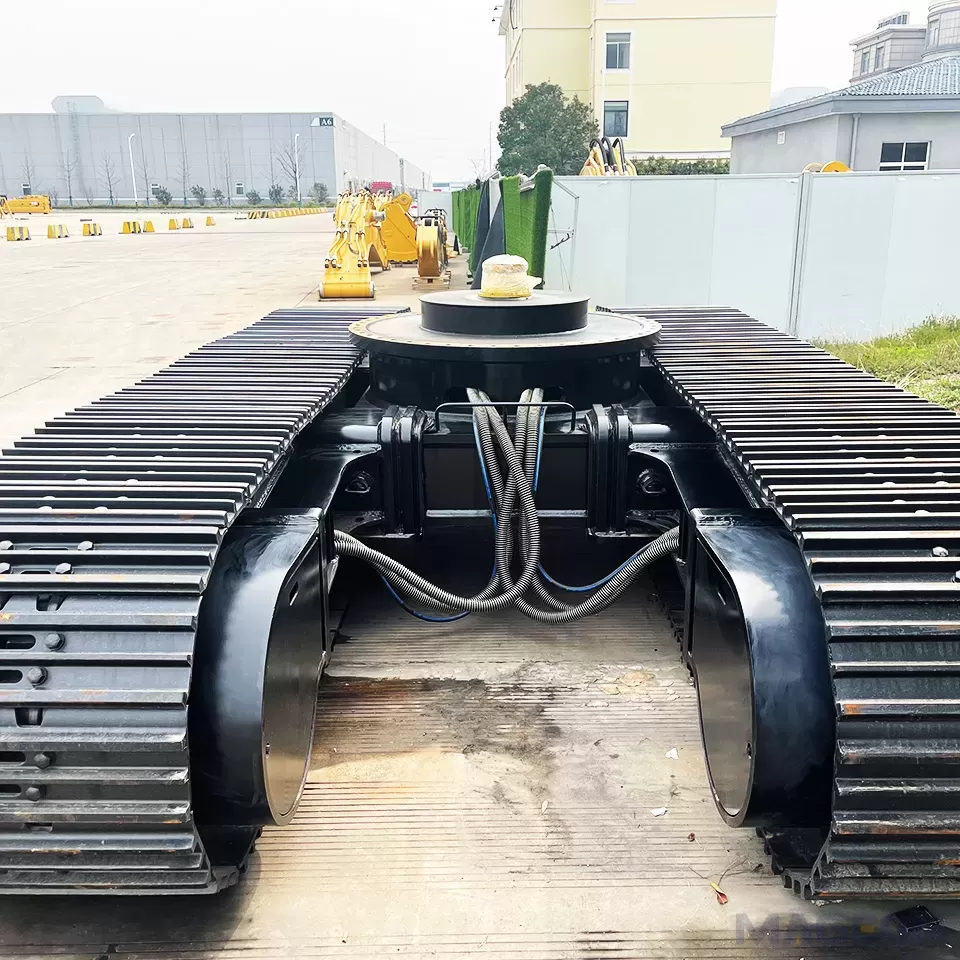
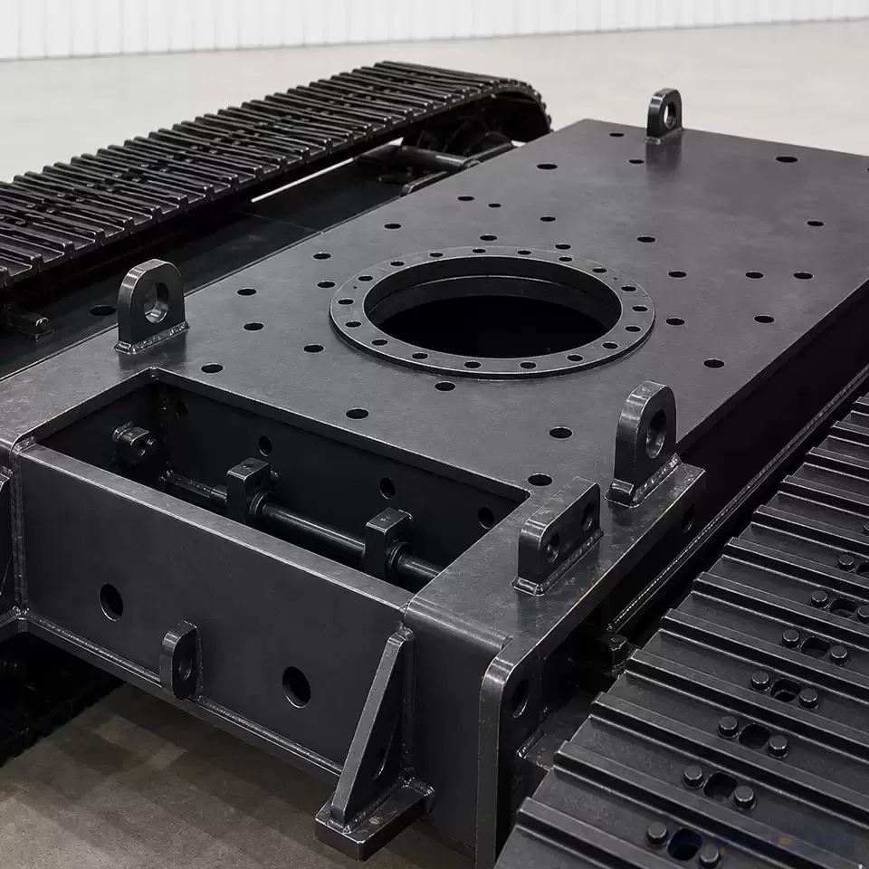
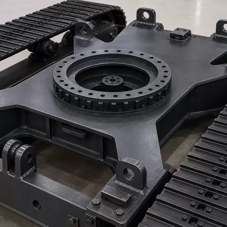
The chassis platform adopts a box-type welded structure, integrating a slewing bearing seat and X-shaped reinforced beam. This design ensures overall structural rigidity, effectively bears the full weight of the upper structure and working loads, and maintains structural stability under complex stress conditions.
2. Power Transmission and Motion Principle
The mechanical energy output by the diesel engine is converted into hydraulic energy through a hydraulic pump, and the speed of the travel motor is controlled through a multi-way valve.
Tracked models: Propulsion is realized through the meshing between drive sprocket teeth and track shoes. The ground contact pressure can be as low as 30 kPa, delivering excellent soft ground passability.
Wheeled models: Steering is realized through a differential mechanism, with a minimum turning radius reaching 80% of the body length, providing flexible maneuverability.
3. Technical Comparison of Travel Modes
(1) Tracked Travel System
Suitable for complex terrain with slopes ≤ 35°.
Equipped with standard anti-derailment devices and automatic tensioning mechanisms.
Widened track shoes can be selected for swamp areas to further reduce ground pressure.
(2) Wheeled Travel System
All-wheel drive models equipped with central tire inflation/deflation system can reach a road speed of 35 km/h.
Steering accuracy reaches ±5°, with high operation flexibility on paved roads.
4. Technical Details of Drive System
(1) Turbocharged Diesel Engine
Meets Stage III emission standards.
Power range covers 80–450 kW.
Equipped with fully electronic fuel injection system for high combustion efficiency.
(2) Hydraulic Transmission Device
Adopts load-sensing variable pump and fixed displacement motor combination.
Realizes stepless speed regulation and power adaptive distribution, automatically adjusting flow output according to load conditions to improve energy utilization efficiency.
(3) Final Drive Mechanism
Planetary gear reducer combined with multi-disc wet brake.
Transmission efficiency ≥ 92%.
Brake torque reserve factor of 1.8, ensuring reliable braking performance under heavy load and slope conditions.
5. Reliability Design System
The reliability design of the crawler chassis system covers three core dimensions:
Track pin surface hardening treatment: Surface hardness reaches HRC 58–62, significantly improving wear resistance and service life.
Double-sealed track roller structure: IP67 protection grade, effectively preventing mud and water intrusion and extending bearing service life.
FEA optimization of fully welded chassis frame: Safety factor ≥ 2.5, ensuring structural reliability under extreme load conditions.
Different configuration schemes can adapt to an ambient temperature range from -40°C to +50°C, with a continuous operation life of 12,000 hours, meeting the requirements of various harsh working environments.
Summary
The excavator crawler track undercarriage system is a comprehensive mechanical system integrating structure, hydraulics and power transmission. Its performance depends on the cooperative matching of multiple subsystems. Understanding the structural composition and operating mechanism helps optimize equipment selection, improve maintenance efficiency and extend overall service life. MAGEON provides professional customized chassis solutions and technical support for construction machinery OEM customers worldwide.
Frequently Asked Questions
Q: What are the core components of an excavator chassis system?
A: The excavator chassis system is mainly composed of three parts: travel system (tracked or wheeled), power transmission unit (engine + hydraulic transmission + travel motor), and load-bearing frame (box-type welded structure with slewing bearing seat). The three subsystems cooperate to complete load bearing, power transmission and walking functions.
Q: What is the working principle of the crawler chassis power transmission?
A: The diesel engine outputs mechanical energy, which is converted into hydraulic energy by the hydraulic pump. The flow is distributed through the multi-way valve to drive the axial piston travel motor, and then the speed is reduced and torque is increased through the final drive reducer to drive the sprocket to rotate. The sprocket meshes with the track chain to push the equipment forward.
Q: What is the difference between tracked and wheeled excavator chassis?
A: Tracked chassis has low ground pressure (as low as 30 kPa), strong terrain adaptability and climbing ability (≤35°), suitable for complex off-road conditions; wheeled chassis has high driving speed (up to 35 km/h), flexible steering and good road mobility, suitable for scenes requiring frequent transfer and paved road operation.
Q: What is a load-sensing hydraulic system?
A: Load-sensing system means the hydraulic pump can automatically adjust the output flow and pressure according to the actual load demand. When the load is small, the output flow is reduced to save energy; when the load is large, the flow is increased to ensure power. It realizes stepless speed regulation and power adaptive distribution, improving energy utilization efficiency.
Q: What is the function of the final drive planetary reducer?
A: The planetary reducer reduces speed and increases torque for the high-speed and low-torque power output by the travel motor, so as to provide sufficient traction for the chassis. It is also integrated with a multi-disc wet brake, with a brake torque reserve factor of 1.8, ensuring reliable braking under heavy load and slope conditions.
Q: Why is surface hardening treatment applied to track pins?
A: Track pins bear long-term repeated friction and impact during operation. Surface hardening treatment (HRC 58–62 surface hardness) can significantly improve surface wear resistance, extend the service life of pins and bushings, and reduce the maintenance frequency of the track assembly.
Q: What does IP67 protection grade mean for track rollers?
A: IP67 means the roller has complete dust-proof ability (6-level dust protection) and can withstand short-term immersion in water within 1 meter depth (7-level water protection). The double-sealed structure effectively prevents mud and water from entering the bearing cavity, ensuring long-term stable operation in harsh environments.
Q: What is the safety factor of the chassis frame and how is it guaranteed?
A: The safety factor of the fully welded chassis frame is ≥ 2.5, which means the structural strength can withstand more than 2.5 times the rated load. It is verified and optimized through finite element analysis (FEA), and the box-type structure plus X-shaped reinforced beam design ensures overall rigidity and structural reliability.
Q: What is the ambient temperature adaptation range of the chassis system?
A: Through targeted material selection and configuration optimization, the chassis can adapt to an ambient temperature range from -40°C to +50°C. Low-temperature resistant materials and seals are used in cold regions, and targeted heat dissipation design is adopted in high-temperature environments, ensuring stable operation under extreme temperature conditions.
Q: What is the typical service life of an excavator undercarriage?
A: Under normal use and standard maintenance conditions, the continuous operation life of the chassis system can reach 12,000 hours. The actual service life is also affected by working conditions, operation habits and maintenance quality. Scientific maintenance can further extend the overall service life.
Applicable products:
Compatible Equipment & Product Applications
This chassis technical framework applies to various crawler and wheeled construction machinery. Main compatible models include:
All tonnage hydraulic crawler excavators
Wheeled excavators and mobile construction equipment
Crawler drilling rigs and piling machinery
Bulldozers and crawler loaders
Special engineering crawler vehicles
Please leave your customization requirements, and we will contact you as soon as possible!
Leave your requirements, we'll get back to you within 24 hours.