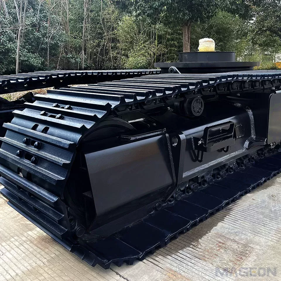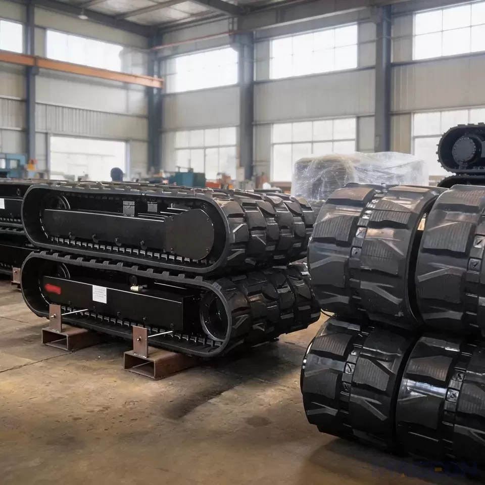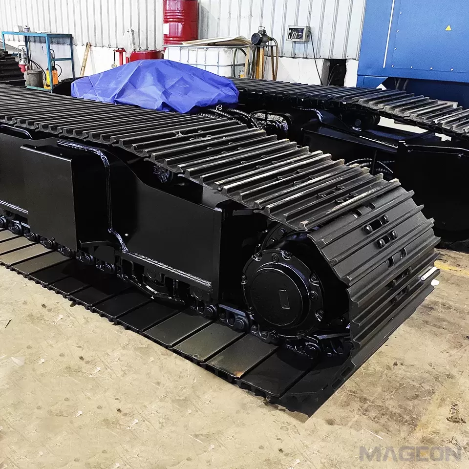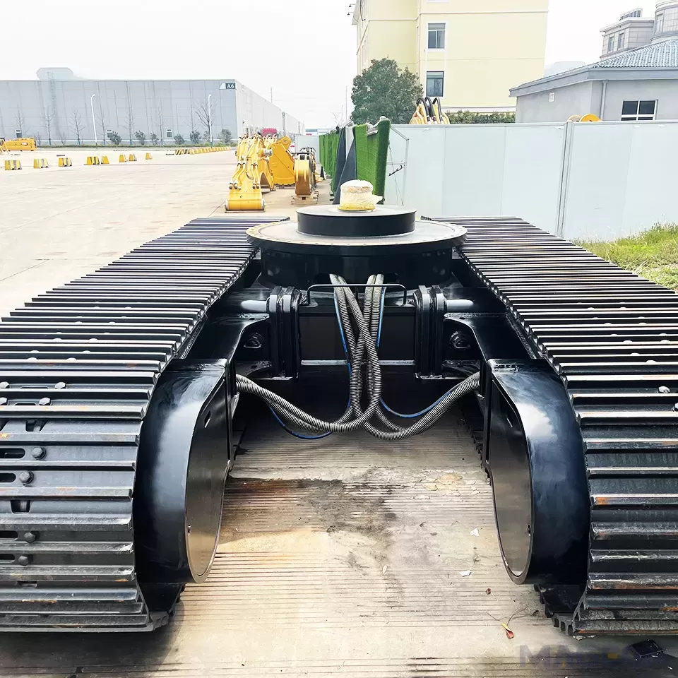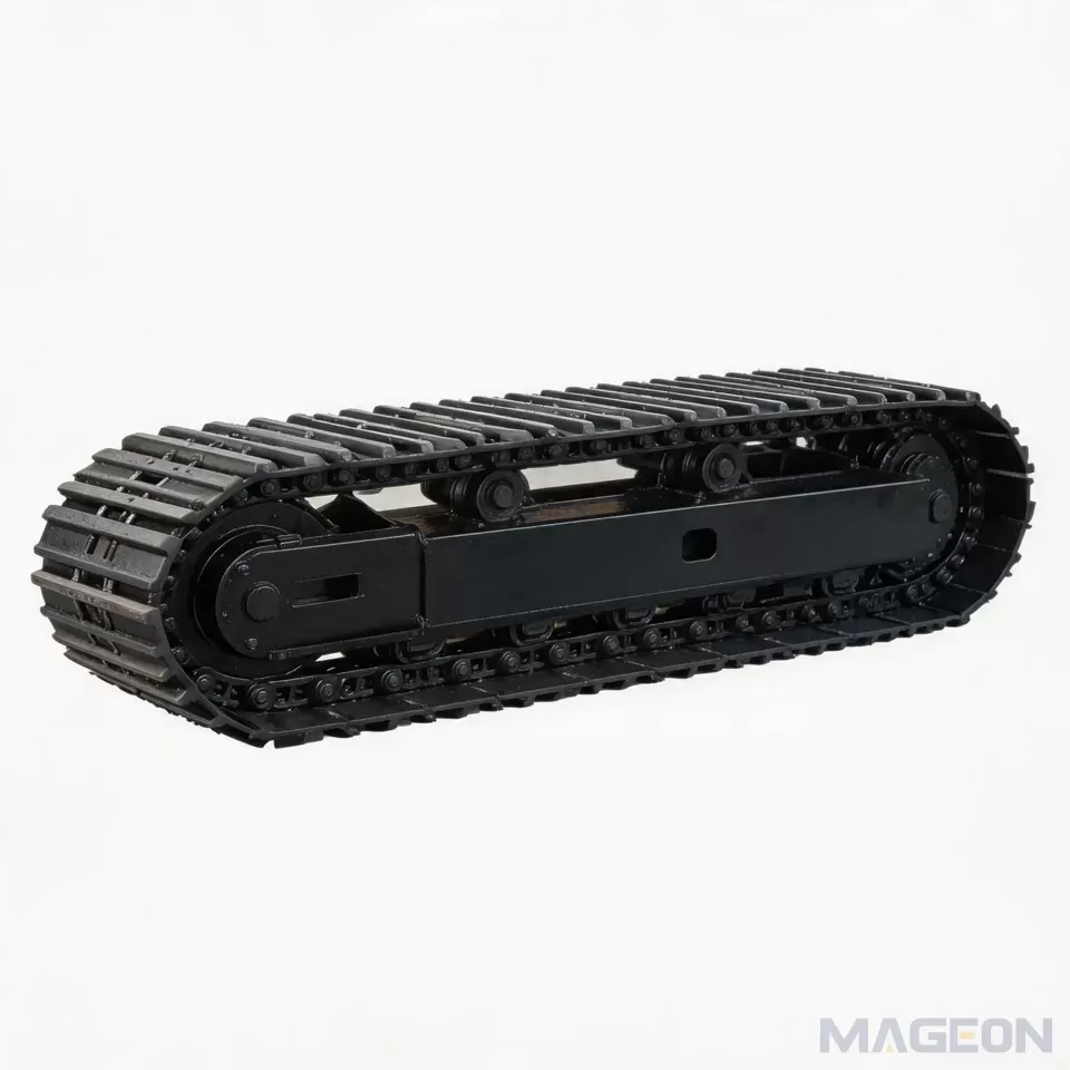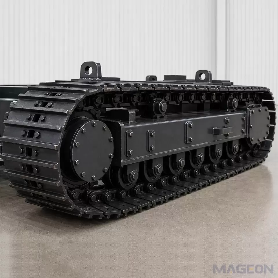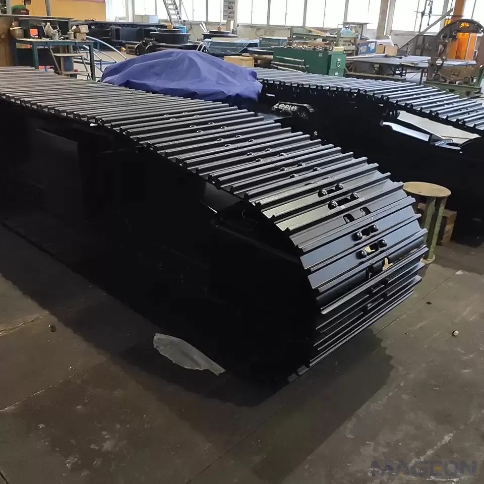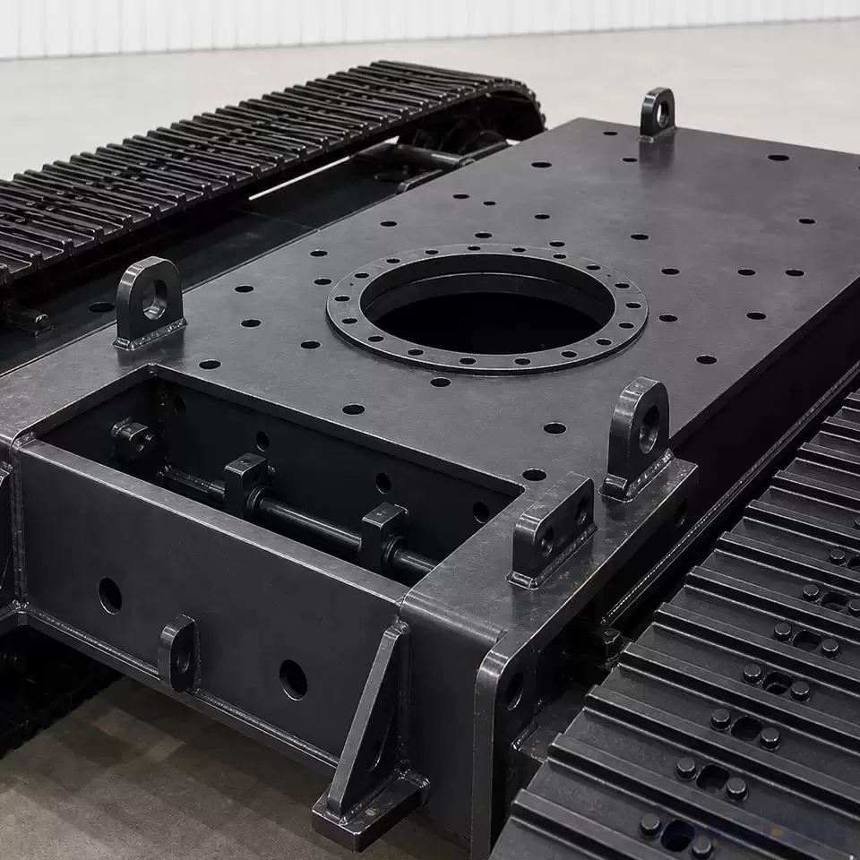

Why Does Center-of-Gravity Location Matter in Crawler Undercarriage Design?
Project Overview:
Conclusion
Center-of-gravity location matters because the undercarriage responds to where the complete machine's mass acts, not only to how much the machine weighs. Longitudinal, lateral, and vertical coordinates must be tied to a clear reference system and to the configurations that will actually be evaluated. They should then be considered with track support geometry, ground conditions, external loads, and duty cycle.
For a technical evaluation or inquiry about complete crawler undercarriage assemblies, provide MAGEON with the equipment layout, mass and load states, CG coordinates, dimensional constraints, terrain, and duty conditions. Project-specific engineering confirmation is still required before any design or operating limit is accepted.
Center-of-gravity location matters because it defines where the weight of the complete machine acts relative to the tracks' ground-contact support region. Two machines can have the same total mass and still place very different loads on the front, rear, left, and right portions of their undercarriages. Those differences affect the design questions that an OEM and undercarriage supplier must evaluate.
The useful input is a traceable set of longitudinal, lateral, and vertical CG coordinates for the configurations that will actually be assessed. Consider them with track geometry, attachments, payload, terrain, operating posture, and external loads.
Direct Answer: Center of Gravity Is a Whole-Machine Input
An undercarriage carries and transmits the effects of the complete machine above it. If the combined CG moves forward, rearward, or to one side, the corresponding contact loads will also be redistributed. If the CG is higher, a slope or lateral force acts through a longer moment arm. The undercarriage therefore needs the mass distribution of the whole machine, not only the weight of the crawler assembly.
CG information therefore belongs in the OEM's design-input package. It helps engineers select load cases and verification methods, but it does not specify track dimensions, structure, or an allowable operating slope by itself.
Define the Center of Gravity Before Evaluating the Undercarriage
The center of gravity is the point through which the resultant gravitational force of the complete machine can be treated as acting for a stated configuration. It is not automatically the geometric center of the chassis. It is also different from the center of pressure, which describes the resultant location of the distributed reaction at the track–ground interface.
Every CG record needs a coordinate system and a machine state. At minimum, the OEM should define the longitudinal, lateral, and vertical axes; the origin and datums; the sign convention; the included equipment; the attachment position; and the loading condition. The coordinate frame should connect whole-machine datums to the documented crawler undercarriage mounting dimensions so that every mass and CG record uses the same reference.
ISO 5005 addresses the determination of CG coordinates for earth-moving machinery under different loading conditions and attachment positions. Its scope reinforces an important project rule: a CG value without its corresponding configuration is incomplete. The project team must still confirm whether that standard is applicable to the machine category and verification plan at hand.
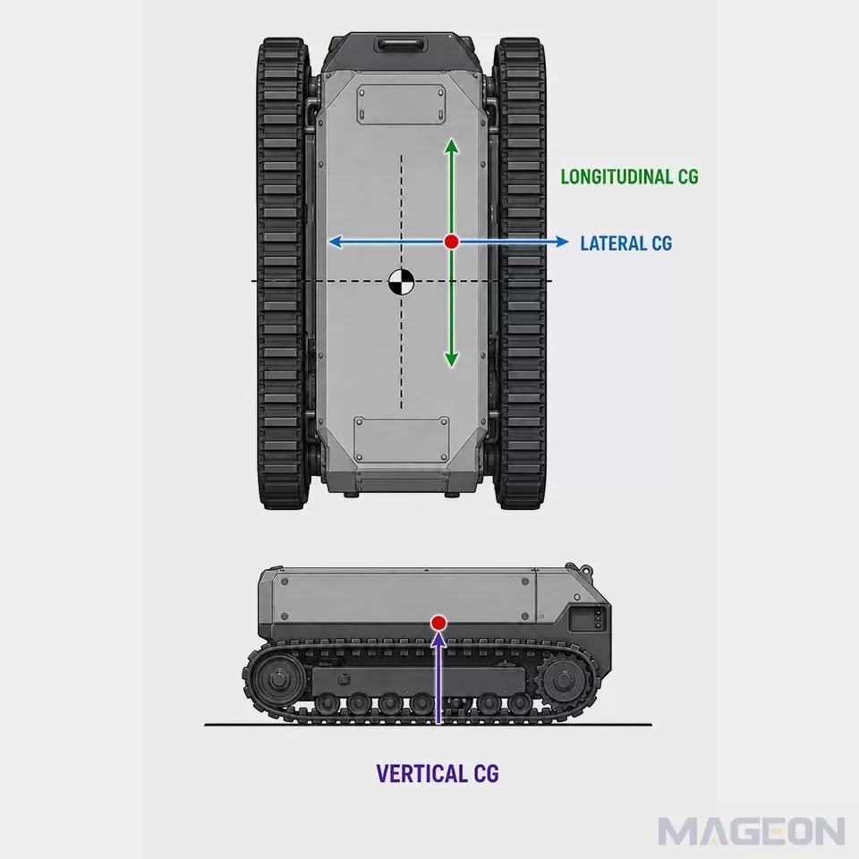
How Longitudinal, Lateral, and Vertical CG Positions Change the Design Question
The three CG coordinates answer different questions. Treating them as one generic “balance” value can hide a critical load case.
| Design question | Related effect | Project confirmation | |
|---|---|---|---|
| Longitudinal | Where does the weight act along the track contact length? | Front-to-rear load distribution and pitch-related margins | Working posture, attachment reach, payload position, contact length |
| Lateral | How is weight divided between the left and right tracks? | Side-to-side track loading and lateral stability assessment | Slew position, side-mounted equipment, cross-slope cases, track spacing |
| Vertical | How high is the combined mass above the support region? | Moment arm under slope, acceleration, or external force |
These directions interact. A centered CG on level ground is different from the same CG shifted laterally on a slope, while an attachment can make a previously modest longitudinal offset important. The coordinate set should expose those combinations before the undercarriage layout is frozen.
How CG Location Changes Track Load Distribution
On firm, level ground in a static condition, total vertical reaction balances machine weight and the reaction moments balance the moment created by the CG position. A longitudinal CG shift therefore tends to move more of the reaction toward one end of the contact region. A lateral shift tends to increase the share carried by one track and reduce the share carried by the other.
That explanation is a starting point, not a complete pressure model. Track contact pressure is rarely uniform in real operation. Roadwheel positions, track stiffness and tension, ground deformation, local support, attachments, motion, and external forces can all change the distribution. The center of pressure may move even though the machine's mass has not changed.
ISO 16754 explicitly limits average ground contact pressure to comparison between crawler machine models and notes that actual operating pressure varies with load, CG position, terrain, track shoe characteristics, and surface conditions. An average value is therefore not evidence that every part of both tracks carries the same load, nor is it a prediction of sinkage, traction, wear, or service life.
How CG Position Enters Stability and Slope Evaluation
For a simplified static check on firm ground, engineers consider where the gravity line projects relative to the effective support boundary. As the machine tilts, or as the CG moves or rises, that projection and the available restoring moment change. This is the geometric reason CG position belongs in a stability assessment.
The crawler undercarriage track gauge defines part of the lateral support geometry, but it does not establish stability by itself. Contact length, actual contact state, machine posture, attachment or payload position, ground strength, slope direction, external forces, acceleration, braking, turning, and track slip may all alter the relevant load case.
A 2024 Journal of Terramechanics study examined static stability of tracked vehicles under multidirectional loading rather than treating rollover or sliding as a single isolated condition. A separate 2025 Agronomy study modeled and tested a specific low-speed tracked robot steering on soft-soil slopes, showing that slope, CG height, track loading, soil behavior, slip, and steering interact. These studies support a system-level evaluation, but their models and test conditions are not universal design limits.
A lower CG may improve a geometric margin in a defined case, but it does not resolve weak ground, an unfavorable offset, an extended load, or a dynamic maneuver. The OEM must evaluate the complete configuration and intended operation.
Why the Relevant CG Changes with Machine Configuration
A crawler machine rarely has only one meaningful configuration. Attachments can raise, lower, extend, retract, or rotate. Payload can be added, released, or shifted. Consumables and stored materials can change mass distribution. A rotating or articulating upper structure can move the combined CG relative to the tracks even when the undercarriage itself does not change.
The CG dataset should therefore be state-based. Identify the configurations that could govern design or operation, then record the mass and CG for each one. Typical categories may include transport, unloaded working, loaded working, attachment extremes, and service positions, but the correct list must come from the actual machine functions and risk assessment.
The heaviest condition is not automatically the most critical; a lighter configuration can create a less favorable CG position. The project team should select credible boundary cases and record why they govern.
What OEMs Should Provide for Engineering Evaluation
The undercarriage evaluation should begin with controlled inputs rather than an isolated total weight. ISO 6016 provides methods for measuring the masses of whole earth-moving machines, equipment, attachments, and components. For a specific OEM project, the responsible engineering team must define the applicable measurement or calculation method and the required accuracy.
| Required machine state | Why it matters | Source or owner | |
|---|---|---|---|
| Coordinate system and datums | Common to every record | Keeps CG, mounting, and contact geometry aligned | Approved layout or interface drawing |
| Total mass and three CG coordinates | Each governing configuration | Establishes gravitational force location | OEM calculation, measurement, or approved data |
| Track support geometry | Proposed undercarriage and contact state | Defines the reference support region | Approved undercarriage drawing and project analysis |
| Attachment, payload, and moving-part positions | Each governing configuration | Explains why mass distribution changes | OEM configuration definition |
| Terrain and duty conditions | Travel, work, turn, slope, and transition cases | Defines external conditions and required verification | Application and risk assessment |
| Verification basis and responsibility | Every design gate | Identifies who checks, approves, and controls revisions |
This focused dataset belongs within the broader technical information required before undercarriage design, not in a disconnected email or an unlabeled drawing. Revision control matters: if a battery pack, counterweight, tank, attachment, payload envelope, or upper structure changes, the mass and CG records may also need revision.
Frequently Asked Questions
Is the center of gravity the same as the geometric center of the machine?
No. The geometric center describes shape or dimensions, while the CG depends on how mass is distributed. Attachments, payload, tanks, batteries, counterweights, and moving structures can place the CG away from the geometric center.
Is total machine mass enough to select a crawler undercarriage?
No. The supplier also needs mass distribution, CG coordinates, support geometry, terrain, duty conditions, and governing configurations.
Does a low center of gravity guarantee crawler stability?
No. CG height is one input. Lateral or longitudinal offset, track contact, ground strength, slope direction, external loads, attachment posture, and dynamic operation can still govern the result.
Why might an OEM need more than one CG record?
Attachments, payload, rotating structures, and consumable levels can move the complete-machine CG. Each credible governing configuration needs an identified value.
Can average ground contact pressure show the load on each track?
Not by itself. An average value is useful for a defined comparison, but it does not show local peaks, front-to-rear variation, left-to-right imbalance, or the effects of operating terrain and motion.
When should the CG evaluation be repeated?
Repeat or review it when a change can materially alter mass, mass position, support geometry, attachments, payload, operating posture, or duty conditions. The project verification plan should define the revision triggers and responsible engineering owner.
Applicable products:
Use Project Verification Before Freezing the Undercarriage
A practical verification loop has four parts:
Define the governing machine configurations and common reference system.
Obtain traceable mass, CG, geometry, terrain, and duty-condition inputs.
Analyze the relevant static and dynamic load cases with methods appropriate to the machine and risk.
Record the assumptions, limits, responsibilities, results, and revision triggers before design release.
The supplier can use approved inputs to evaluate the proposed crawler assembly and interfaces. The OEM remains responsible for defining the upper structure, attachment motion, payload, intended operating envelope, and system-level validation. Responsibilities should be explicit rather than implied by a quotation or preliminary layout.
Please leave your customization requirements, and we will contact you as soon as possible!
Leave your requirements, we'll get back to you within 24 hours.